Stairs, a straight stair run, a mezzanine stair, an ADA ramp at 1:12, a handrail, a guardrail, square columns at 8 and 12in, and - new - L-shaped and U-shaped switchback stairs at 36 and 44in and spiral stairs at 60, 72 and 84in diameter, each drawn left-hand with a right-hand mirror - fifteen circulation and structural CAD blocks whose dimensions are the code question. The ramp runs 171in for a single 14in rise at 1:12, which is the number that decides whether the ramp fits the site or needs a landing. The switchbacks turn the same 108in floor-to-floor rise inside a 102in square or a 72x102in well instead of the 20-odd feet a straight run wants, which is the whole reason to draw one. Free DXF downloads drawn to scale in inches.
15 blocks, 22 downloads on this page. DXF R2018, drawn in inches. Free, no signup.
DWG (R2000, converted from the DXF). PNG is the plan-view preview.
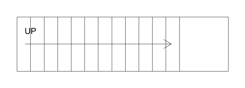
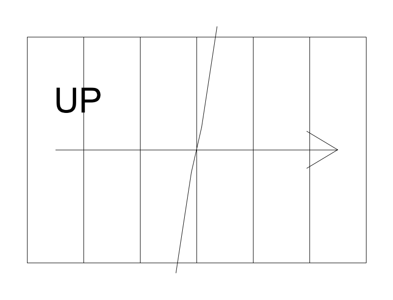
A straight-run stair drawn in plan with treads and nosings, used on both commercial and residential sheets. The plan version establishes the run length that has to fit the floor plate, which is usually the constraint that forces a stair to be redesigned as a switchback.
The 44in default width is the commercial egress stairway minimum, dropping to 36in only where the occupant load served is under 50, and the 36-72in range covers both plus a wide monumental run. tread_w defaults to the 11in commercial minimum tread depth, with 9-14in covering shallower residential treads and deeper low-pitch runs; the treads count runs 2-24, so drawn run length is simply tread count times tread depth.
Datum is the near-left corner at the bottom of the run, developing toward +X: six treads at 11in is exactly the 66in default length, while the 48in cross dimension carries the 44in width plus stringer allowance. The UP arrow and break line are annotation and have to be added over the block.
A stair on an accessible route takes handrail on each side while a residential flight usually shows one, and guardrail goes at the open side and around the floor opening above, so the three get placed as a set on one plan.
| Plan footprint (W x H) | 66in x 44in |
|---|---|
| Units | inches |
| DXF version | R2018 |
| Insertion datum | near-left corner (bottom of run) |
| Parameter | Default | Range / options |
|---|---|---|
| Treads | 6 | 2–24 |
| Tread width | 11in | 9in–14in |
| Width | 44in | 36in–72in |
A straight-run stair serving a mezzanine, platform or equipment level, drawn with stringers, riser lines, a top landing and an UP arrow. In plan it resolves how people reach the upper level, and it is usually the first thing that has to move when the layout underneath changes.
The plotted 171.6in at defaults is not the run. Twelve treads at 11in gives a 132in run, and the block adds a top landing sized at 0.9 times the stair width. Riser count comes from none of these parameters; it comes from floor-to-floor height, so treads and risers have to be reconciled against the section.
Near-left corner insertion at the bottom of the run means the block grows away from the datum as tread count rises, so set treads and tread_w before placing it against the floor opening above. Note the two rule sets inside the range: an 11in tread and 44in width are means-of-egress proportions, while the 9in bottom of the tread range is below the minimum tread depth in both the egress rules and the OSHA fixed-stair rules, making it a value for drawing an existing condition rather than designing a new one.
Drawn against the rack bay and the mezzanine storage it serves. The coordination that bites is where the bottom lands: the landing has to open into circulation space, not into a rack aisle or a staged pallet.
| Plan footprint (W x H) | 171.6in x 44in |
|---|---|
| Units | inches |
| DXF version | R2018 |
| Insertion datum | near-left corner (bottom of run) |
| Parameter | Default | Range / options |
|---|---|---|
| Treads | 12 | 6–24 |
| Tread width | 11in | 9in–14in |
| Width | 44in | 36in–60in |
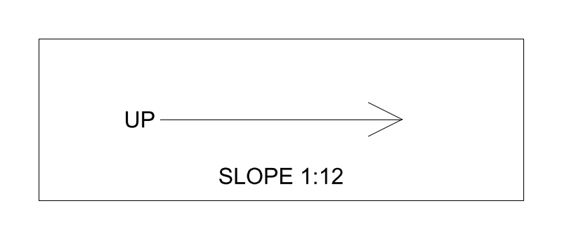
A sloped accessible route drawn in plan with its direction of travel indicated: entry ramps at a grade change, stage and platform approaches, ramps between split levels in a tenant space. The slope, not the length, is what a plan reviewer checks first.
The slope parameter is the run-to-rise denominator, so the default 12 is a 1:12 running slope and 20 is 1:20, shallow enough that the element stops being a ramp at all. Settings of 8 or 10 are steeper than 1:12 and belong to existing conditions or non-accessible service ramps.
The 360in run maximum is not arbitrary: at 1:12 it produces a 30in rise, the maximum for a single ramp run, and the 144in default gives a 12in rise. Datum is the near-left, bottom-of-ramp corner climbing toward +X, so verify the arrow after rotating. Note that the 36-96in width is drawn edge to edge, which is not the same as clear width between handrails.
Drawn with handrail on both sides wherever the run has enough rise to require them, and with the landings at each end, which the block does not include and which have to be added as separate geometry.
| Plan footprint (W x H) | 144in x 48in |
|---|---|
| Units | inches |
| DXF version | R2018 |
| Insertion datum | near-left (bottom-of-ramp) corner |
| Parameter | Default | Range / options |
|---|---|---|
| Run | 144in | 48in–360in |
| Width | 48in | 36in–96in |
| Slope | 12 | 8–20 |
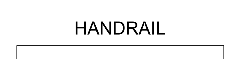
A graspable rail drawn in plan beside the stair or ramp run it serves. The plan is where the extensions past the top and bottom of the run get drawn, and those extensions are the detail most often omitted and most often caught in review.
48in default run across a 24-240in (20ft) range, but real lengths come from the flight rather than round numbers: a ramp run plus a 12in extension at each end, or a stair flight plus its extensions. The 8.5in bbox depth is the drawn rail-and-bracket band off the wall face.
Insertion is the near-left end with the run developing toward +X, and the 48in footprint length equals the run exactly, so a rail placed along a stair or ramp edge lines up without an offset correction. Copy and mirror for the far side rather than drawing the second run by hand.
Copied in pairs onto stairs and ramp, both of which take a rail on each side where they serve an accessible route, and butted into guardrail wherever the run also sits at an open edge.
| Plan footprint (W x H) | 48in x 4.5in |
|---|---|
| Units | inches |
| DXF version | R2018 |
| Insertion datum | start (near-left) end, runs +X |
| Parameter | Default | Range / options |
|---|---|---|
| Run | 48in | 24in–240in |
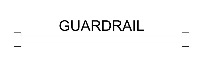
A guard at an open edge: mezzanine perimeters, dock faces, stair and floor openings, roof hatch landings, equipment platforms. In plan it draws as a line with posts, and the plan question it answers is where the guard starts, where it stops, and where it hands off to a gate or a stair rail.
48in default run with a 24-360in (30ft) range. In practice post spacing rather than total length drives the layout, so long edges get built from several instances placed end to end instead of one stretched 30ft run.
Datum is the start (near-left) end running toward +X. The 50 x 7.5in footprint extends 1in past the nominal run at each end and 7.5in for post and base plate, which is the dimension that matters at a slab edge where the base plate has to land on structure.
Meets handrail at the top of stairs, where the guard continues around the floor opening and the graspable rail terminates into it.
| Plan footprint (W x H) | 48in x 4in |
|---|---|
| Units | inches |
| DXF version | R2018 |
| Insertion datum | start (near-left) end, runs +X |
| Parameter | Default | Range / options |
|---|---|---|
| Run | 48in | 24in–360in |
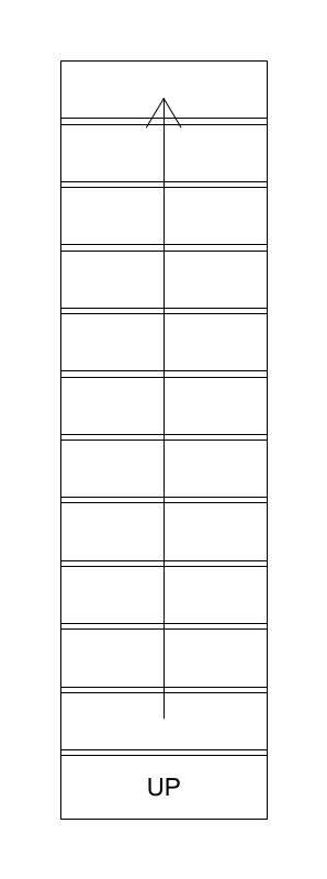
| Plan footprint (W x H) | 36in x 132in |
|---|---|
| Units | inches |
| DXF version | R2018 |
| Insertion datum | near-left corner (bottom of run) |
| Parameter | Default | Range / options |
|---|---|---|
| Width | 36in | 30in–48in |
| Tread | 11in | 10in–14in |
| Risers | 12in | 3in–20in |
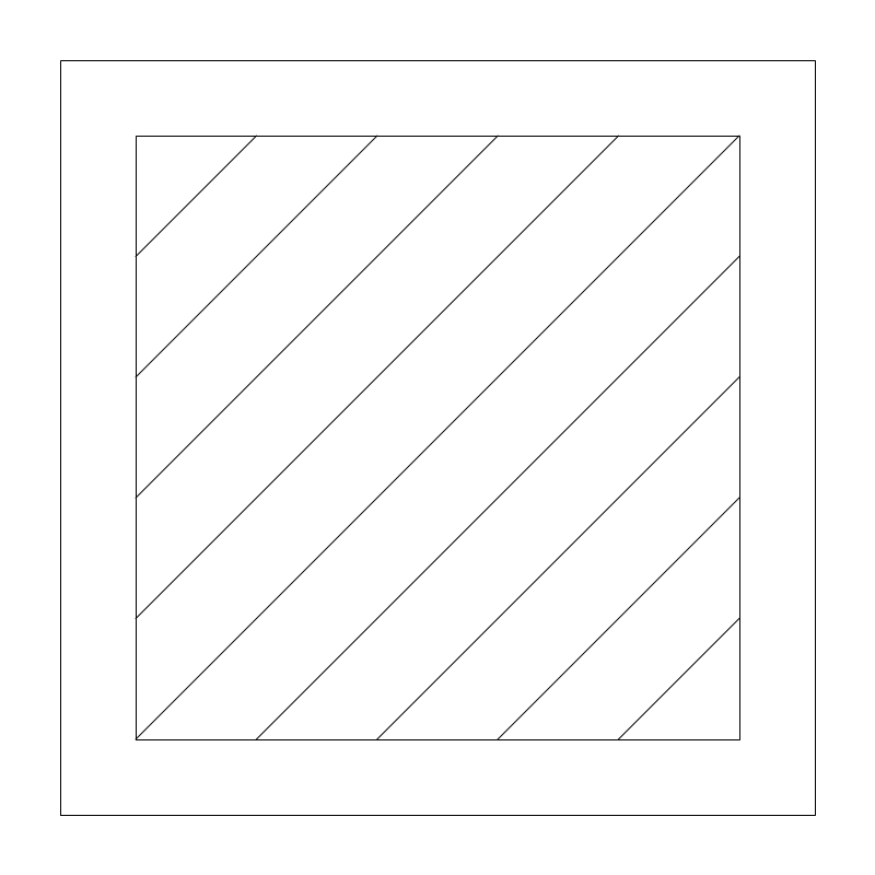
| Plan footprint (W x H) | 8in x 8in |
|---|---|
| Units | inches |
| DXF version | R2018 |
| Insertion datum | column center |
| Parameter | Default | Range / options |
|---|---|---|
| Size | 8in | 6in–24in |
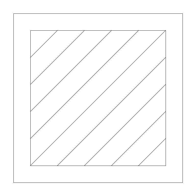
| Plan footprint (W x H) | 12in x 12in |
|---|---|
| Units | inches |
| DXF version | R2018 |
| Insertion datum | column center |
| Parameter | Default | Range / options |
|---|---|---|
| Size | 12in | 6in–24in |
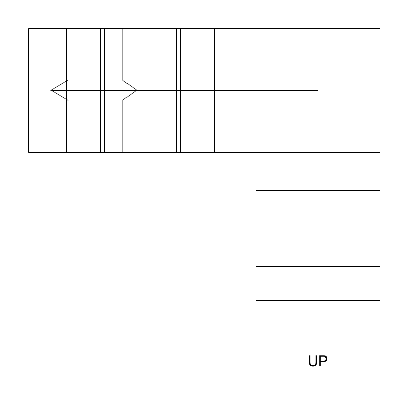
An L-shaped stair: two straight flights meeting at a quarter-turn landing, drawn in plan with treads, nosings and the landing. It is the shape you reach for when a straight run will not fit the floor plate - it turns the same floor-to-floor rise through 90 degrees and tucks into a corner, and the landing doubles as the code-required break in a tall rise.
The flight width is the family split: 36in is the residential minimum and 44in the commercial egress minimum at an occupant load of 50 or more. Default rise is 108in floor to floor at an 11in tread, which is what produces the 102in and 110in square footprints; rise adjusts 36-168in and tread 10-14in, and the landing stays square at the flight width, which is the code minimum landing depth.
Datum is the near-left corner at the bottom of the first flight. The block is drawn left-hand: you climb away from the datum and turn LEFT at the landing. The right-hand member is the mirror, and mirroring is not free on a stair - the handrail, the UP arrow and the break line all have to follow the turn, so take the handed block rather than mirroring this one. The UP arrow and break line are annotation and go over the block.
A handrail goes on each side of a commercial flight and usually one side of a residential one; guardrail runs the open side and returns around the floor opening above. Place the three as a set, and put the stair's landing on the same grid line as the floor opening it lands in.
| Plan footprint (W x H) | 102in x 102in |
|---|---|
| Units | inches |
| DXF version | R2018 |
| Insertion datum | near-left corner of the bounding box; first flight climbs +Y along the RIGHT edge, square landing top-right, second flight runs -X along the top edge -- turn LEFT going up |
| Parameter | Default | Range / options |
|---|---|---|
| Width | 36in | 36in–40in |
| Rise | 108in | 36in–168in |
| Tread | 11in | 10in–14in |
Also: Default Right hand
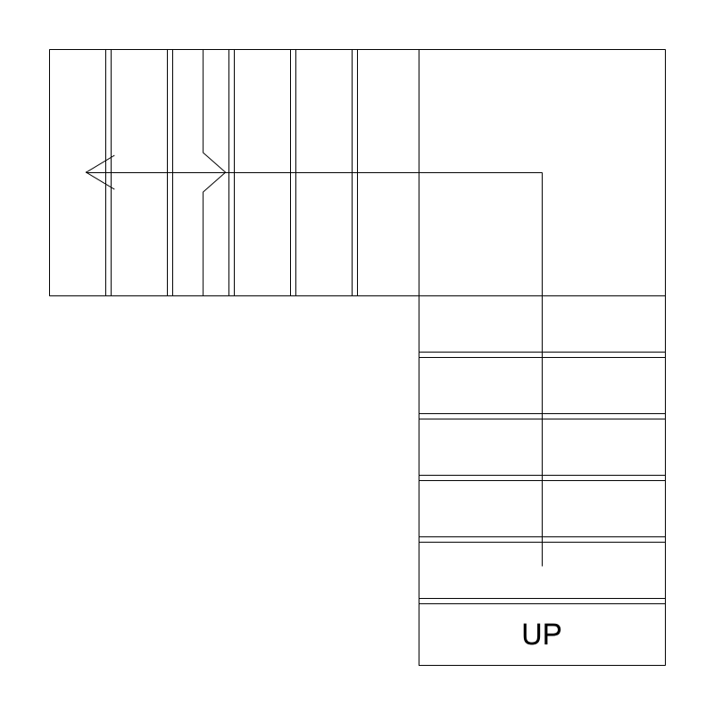
An L-shaped stair: two straight flights meeting at a quarter-turn landing, drawn in plan with treads, nosings and the landing. It is the shape you reach for when a straight run will not fit the floor plate - it turns the same floor-to-floor rise through 90 degrees and tucks into a corner, and the landing doubles as the code-required break in a tall rise.
The flight width is the family split: 36in is the residential minimum and 44in the commercial egress minimum at an occupant load of 50 or more. Default rise is 108in floor to floor at an 11in tread, which is what produces the 102in and 110in square footprints; rise adjusts 36-168in and tread 10-14in, and the landing stays square at the flight width, which is the code minimum landing depth.
Datum is the near-left corner at the bottom of the first flight. The block is drawn left-hand: you climb away from the datum and turn LEFT at the landing. The right-hand member is the mirror, and mirroring is not free on a stair - the handrail, the UP arrow and the break line all have to follow the turn, so take the handed block rather than mirroring this one. The UP arrow and break line are annotation and go over the block.
A handrail goes on each side of a commercial flight and usually one side of a residential one; guardrail runs the open side and returns around the floor opening above. Place the three as a set, and put the stair's landing on the same grid line as the floor opening it lands in.
| Plan footprint (W x H) | 110in x 110in |
|---|---|
| Units | inches |
| DXF version | R2018 |
| Insertion datum | near-left corner of the bounding box; first flight climbs +Y along the RIGHT edge, square landing top-right, second flight runs -X along the top edge -- turn LEFT going up |
| Parameter | Default | Range / options |
|---|---|---|
| Width | 44in | 42in–48in |
| Rise | 108in | 36in–168in |
| Tread | 11in | 10in–14in |
Also: Default Right hand
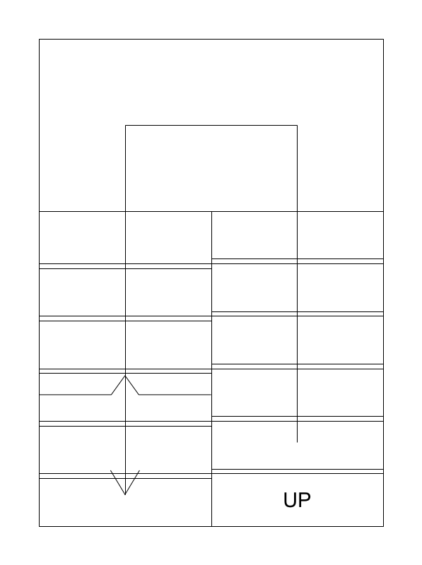
A U-shaped switchback stair: two parallel flights running opposite ways around a half-turn landing, drawn in plan. It is the most floor-efficient stair shape there is - it returns you to the same wall, so the stair well is a single rectangle roughly two flight-widths across, which is why it is the default in stair towers, apartment buildings and anywhere the stair is stacked floor over floor.
36in residential, 44in commercial egress, same as the L. Default 108in rise at an 11in tread gives the 72x102in and 88x110in wells - note the well is only about two flight widths wide, which is the whole point of the shape. Rise adjusts 36-168in, tread 10-14in. The half-turn landing is full flight width, the code minimum.
Datum is the near-left corner at the bottom of the up flight. Drawn left-hand: you climb away from the datum and the landing turns you LEFT, back down the parallel flight. Take the right-hand member rather than mirroring, for the same reason as the L - the handrail, arrow and break line have to turn with it. Stacked floor over floor, the well is one shaft, so align it on the same grid line on every level.
A handrail goes on each side of a commercial flight and usually one side of a residential one; guardrail runs the open side and returns around the floor opening above. Place the three as a set, and put the stair's landing on the same grid line as the floor opening it lands in.
| Plan footprint (W x H) | 72in x 102in |
|---|---|
| Units | inches |
| DXF version | R2018 |
| Insertion datum | near-left corner of the bounding box; first flight climbs +Y in the RIGHT bay, landing across the top, second flight returns -Y in the LEFT bay -- two LEFT turns going up |
| Parameter | Default | Range / options |
|---|---|---|
| Width | 36in | 36in–40in |
| Rise | 108in | 36in–168in |
| Tread | 11in | 10in–14in |
Also: Default Right hand
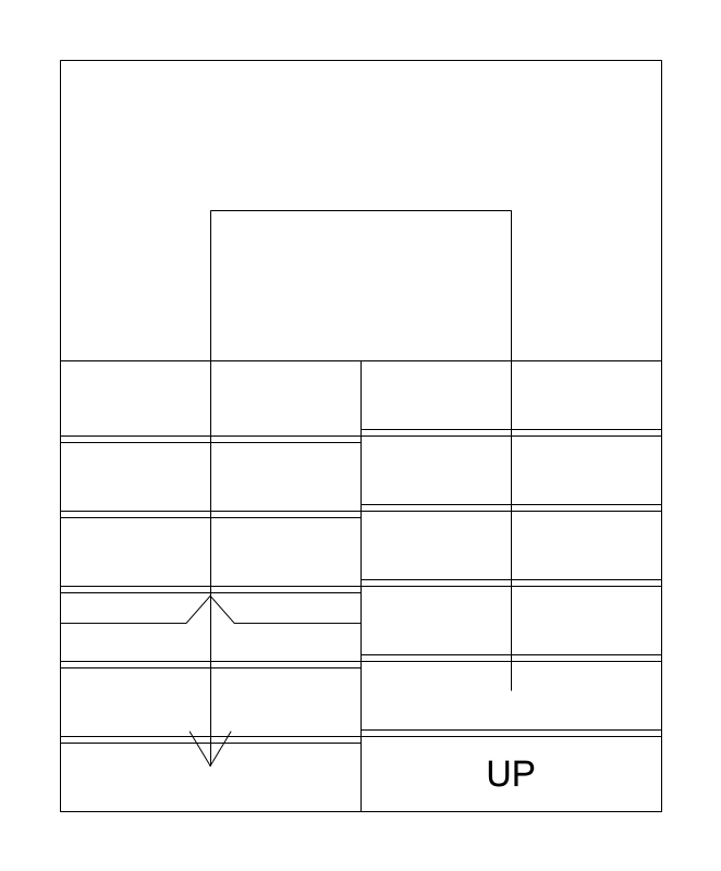
A U-shaped switchback stair: two parallel flights running opposite ways around a half-turn landing, drawn in plan. It is the most floor-efficient stair shape there is - it returns you to the same wall, so the stair well is a single rectangle roughly two flight-widths across, which is why it is the default in stair towers, apartment buildings and anywhere the stair is stacked floor over floor.
36in residential, 44in commercial egress, same as the L. Default 108in rise at an 11in tread gives the 72x102in and 88x110in wells - note the well is only about two flight widths wide, which is the whole point of the shape. Rise adjusts 36-168in, tread 10-14in. The half-turn landing is full flight width, the code minimum.
Datum is the near-left corner at the bottom of the up flight. Drawn left-hand: you climb away from the datum and the landing turns you LEFT, back down the parallel flight. Take the right-hand member rather than mirroring, for the same reason as the L - the handrail, arrow and break line have to turn with it. Stacked floor over floor, the well is one shaft, so align it on the same grid line on every level.
A handrail goes on each side of a commercial flight and usually one side of a residential one; guardrail runs the open side and returns around the floor opening above. Place the three as a set, and put the stair's landing on the same grid line as the floor opening it lands in.
| Plan footprint (W x H) | 88in x 110in |
|---|---|
| Units | inches |
| DXF version | R2018 |
| Insertion datum | near-left corner of the bounding box; first flight climbs +Y in the RIGHT bay, landing across the top, second flight returns -Y in the LEFT bay -- two LEFT turns going up |
| Parameter | Default | Range / options |
|---|---|---|
| Width | 44in | 42in–48in |
| Rise | 108in | 36in–168in |
| Tread | 11in | 10in–14in |
Also: Default Right hand
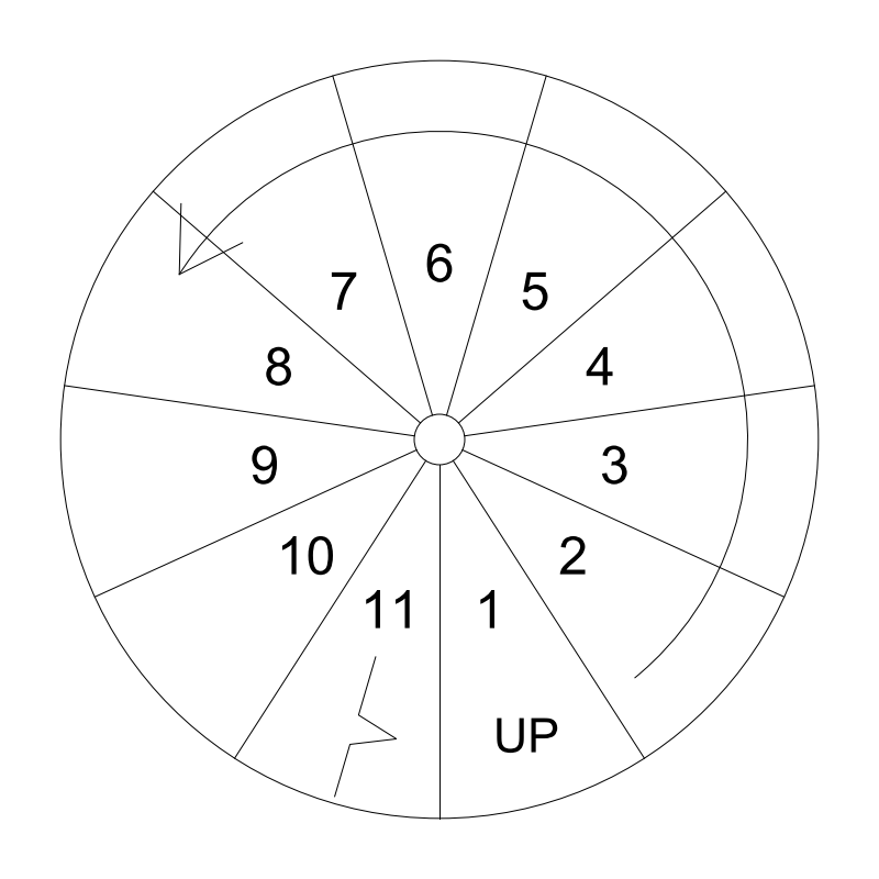
A spiral stair drawn in plan: treads radiating from a centre column, with the walking line shown. It is the smallest stair that connects two floors - which is also its limitation. A spiral is a secondary stair: a loft, a roof hatch, a mezzanine that serves a small area. It is not an accessible route and, in most codes, not a required means of egress except from a very small space.
60in diameter, the smallest published and the usual residential minimum. Rise defaults to 108in floor to floor and adjusts 36-168in; the diameter adjusts 60-66in. At 60in the 26in clear walking width IRC asks for is met with very little to spare, so check it before narrowing anything.
Datum is the centre of the column, not a corner - it drops straight onto the centre point you pick, and the circle is the finished plan extent. Drawn left-hand, meaning it winds counter-clockwise as you climb; the right-hand member winds clockwise. Which hand you want depends on which way you arrive at the top, and getting it wrong puts the walking line on the wrong side of the opening, so check the upper floor first.
A spiral takes a continuous handrail on the outside of the walking line and a guardrail around the floor opening it lands in. It needs no landing, which is why it fits where the L and U stairs do not.
| Plan footprint (W x H) | 60in x 60in |
|---|---|
| Units | inches |
| DXF version | R2018 |
| Insertion datum | near-left corner of the bounding square (pole at centre); entry tread at the bottom, climbs counter-clockwise -- turn LEFT going up |
| Parameter | Default | Range / options |
|---|---|---|
| Diameter | 60in | 60in–66in |
| Rise | 108in | 36in–168in |
Also: Default Right hand
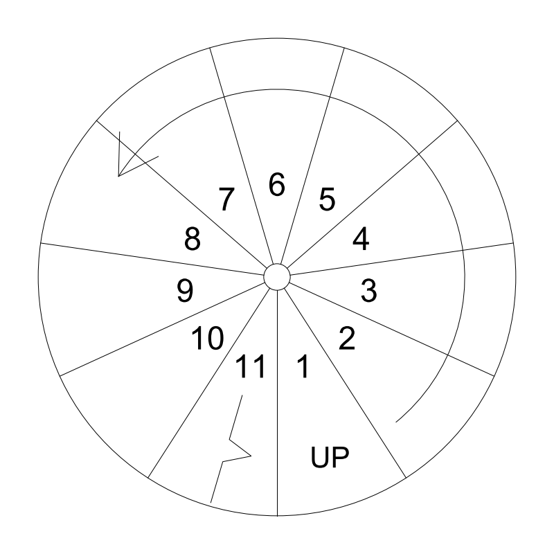
A spiral stair drawn in plan: treads radiating from a centre column, with the walking line shown. It is the smallest stair that connects two floors - which is also its limitation. A spiral is a secondary stair: a loft, a roof hatch, a mezzanine that serves a small area. It is not an accessible route and, in most codes, not a required means of egress except from a very small space.
72in diameter - the comfortable residential and light-commercial size, and the one to default to if the space allows it. Diameter adjusts 66-78in, rise 36-168in at 108in default. The extra foot over the 60in buys real tread depth at the walking line, which is where a spiral is actually uncomfortable.
Datum is the centre of the column, not a corner - it drops straight onto the centre point you pick, and the circle is the finished plan extent. Drawn left-hand, meaning it winds counter-clockwise as you climb; the right-hand member winds clockwise. Which hand you want depends on which way you arrive at the top, and getting it wrong puts the walking line on the wrong side of the opening, so check the upper floor first.
A spiral takes a continuous handrail on the outside of the walking line and a guardrail around the floor opening it lands in. It needs no landing, which is why it fits where the L and U stairs do not.
| Plan footprint (W x H) | 72in x 72in |
|---|---|
| Units | inches |
| DXF version | R2018 |
| Insertion datum | near-left corner of the bounding square (pole at centre); entry tread at the bottom, climbs counter-clockwise -- turn LEFT going up |
| Parameter | Default | Range / options |
|---|---|---|
| Diameter | 72in | 66in–78in |
| Rise | 108in | 36in–168in |
Also: Default Right hand
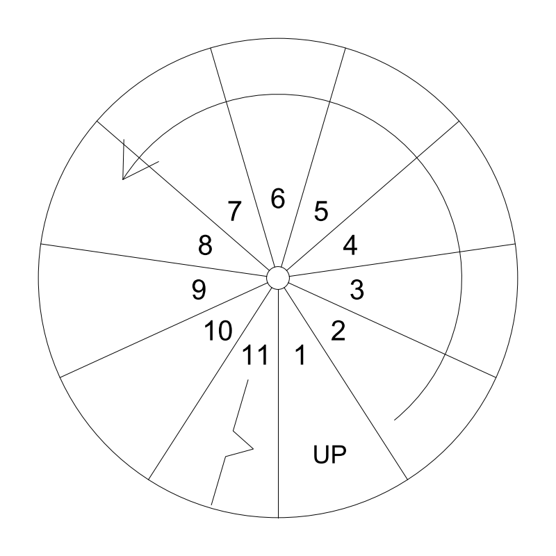
A spiral stair drawn in plan: treads radiating from a centre column, with the walking line shown. It is the smallest stair that connects two floors - which is also its limitation. A spiral is a secondary stair: a loft, a roof hatch, a mezzanine that serves a small area. It is not an accessible route and, in most codes, not a required means of egress except from a very small space.
84in diameter, the largest published. Diameter adjusts 78-96in, rise 36-168in at 108in default. At this size the treads are deep enough to carry furniture up, which is the practical reason to spend the floor area - a 60in spiral will not pass a sofa.
Datum is the centre of the column, not a corner - it drops straight onto the centre point you pick, and the circle is the finished plan extent. Drawn left-hand, meaning it winds counter-clockwise as you climb; the right-hand member winds clockwise. Which hand you want depends on which way you arrive at the top, and getting it wrong puts the walking line on the wrong side of the opening, so check the upper floor first.
A spiral takes a continuous handrail on the outside of the walking line and a guardrail around the floor opening it lands in. It needs no landing, which is why it fits where the L and U stairs do not.
| Plan footprint (W x H) | 84in x 84in |
|---|---|
| Units | inches |
| DXF version | R2018 |
| Insertion datum | near-left corner of the bounding square (pole at centre); entry tread at the bottom, climbs counter-clockwise -- turn LEFT going up |
| Parameter | Default | Range / options |
|---|---|---|
| Diameter | 84in | 78in–96in |
| Rise | 108in | 36in–168in |
Also: Default Right hand
Standards are listed for drafting context only. A symbol drawn to a convention is not a compliance determination - verify against the governing code and the specified product. See the license and terms.
Straight runs, switchbacks and spirals drawn to the dimensions plan review will check. Open one in the editor or take the DXF.
Every category, every MEP orientation, DXF R2018, sorted into folders. Tell us where to send it and the download starts immediately.
If nothing happened, click here to grab the ZIP.