Seventeen door CAD blocks in plan: single swing at 26, 28, 30, 32 and 36in, double swing at 72in, three double-acting doors at 30/36/42in, pocket at 32in, bifold at 48/60/72/96in, a 72in bypass pair, an overhead garage door and a roll-up. The swing and double-acting doors carry their arc, which is the part of a door block that actually governs the layout, since the clear floor a door needs is the arc, not the leaf. The five single swings are the residential door schedule in one family: 26 and 28in for a closet or a linen door, 30in for a bedroom, 32in where a 32in clear opening is the target, 36in where an accessible route passes through. Free DXF downloads.
17 blocks, 17 downloads on this page. DXF R2018, drawn in inches. Free, no signup.
DWG (R2000, converted from the DXF). PNG is the plan-view preview.
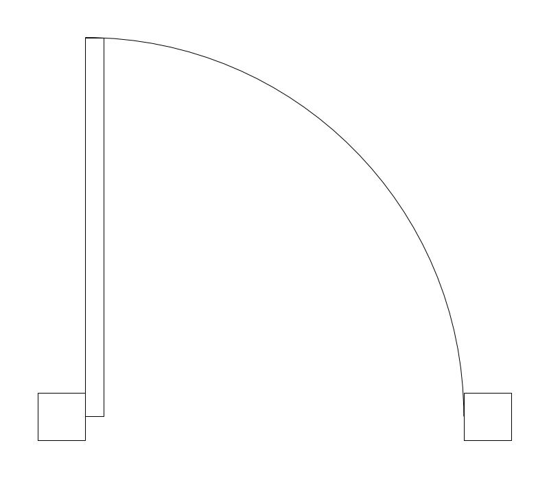
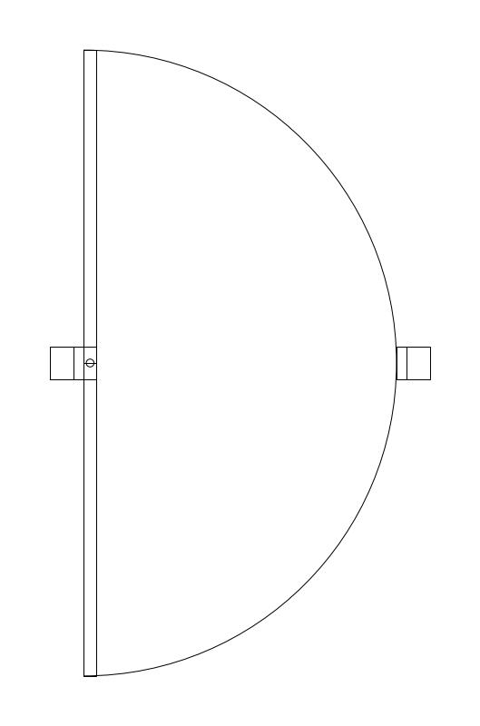
The single leaf with its swing arc, and the most-placed opening on any floor plan: bedrooms, private offices, single-occupant restrooms, corridor doors off a lobby. The arc is the working half of the symbol, since that is what a reviewer reads to confirm the leaf does not foul a fixture, a casework run, or a facing door.
36in is the widest common single leaf and the usual pick where an accessible route passes through, since a 36in leaf leaves about 34in clear with the door open 90 degrees. The 24-48in range reaches down to closet and utility leaves and up to oversize leaves at equipment rooms.
Insertion is the hinge point on the wall centerline, so the block lands on a wall snap and the hand and swing_out flags flip the leaf instead of forcing a mirror. The 45 x 38.2in footprint is mostly arc, so it selects far larger than the opening it represents; keep it on A-DOOR.
Checked against grab-bar-36 and fixture layouts in toilet rooms, where the swing arc and the maneuvering clearance in front of the door compete for the same square feet of floor.
| Plan footprint (W x H) | 45in x 38.25in |
|---|---|
| Units | inches |
| DXF version | R2018 |
| Insertion datum | hinge point on wall centerline |
| Parameter | Default | Range / options |
|---|---|---|
| Width | 36in | 24in–48in |
| Hand | left | left / right |
| Swing direction | false | true / false |
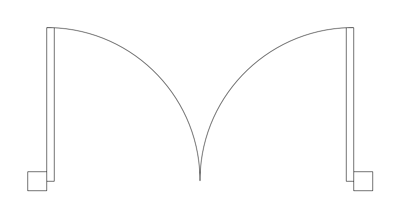
A pair of swinging leaves with both arcs drawn: conference room entries, assembly-space doors, main entrances, and residential French openings. Both arcs are drawn because the combined sweep of an active pair is what governs the clear floor area, and a single-leaf symbol would understate it.
The 72in default is two 36in leaves. The 48-96in range spans a pair of 24in leaves at a narrow utility opening up to two 48in leaves at a main entry, but a pair never doubles accessible clear width: at least one active leaf has to carry the full clear opening on its own.
Insertion is the left jamb on the wall centerline rather than either hinge, so both leaves develop from a single point and stay symmetric as the width changes. swing_out flips the whole pair to the far wall face for out-swinging exterior sets; footprint 81 x 38.2in.
Often centered on the same rear elevation as window-double-60, where the paired opening and the mulled pair are drawn to a shared centerline so the exterior reads as one composition.
| Plan footprint (W x H) | 81in x 38.25in |
|---|---|
| Units | inches |
| DXF version | R2018 |
| Insertion datum | left jamb on wall centerline |
| Parameter | Default | Range / options |
|---|---|---|
| Width | 72in | 48in–96in |
| Swing direction | false | true / false |
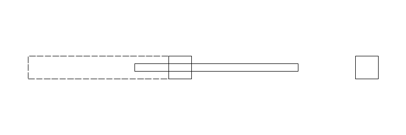
A leaf that retracts into the wall cavity, used where a swing arc will not fit: powder rooms, closets tucked behind a fixture, pass-throughs between a kitchen and a utility space. The plan symbol earns its place by reserving the pocket, which consumes a run of stud bays and rules out blocking, receptacles, and piping over that length of wall.
32in default across a 24-48in range, but the number that governs layout is the 68.5in footprint rather than the leaf: the cavity has to be about twice the leaf width to swallow the door plus track hardware, so a 48in pocket leaf wants better than 8ft of uninterrupted wall.
Datum is the opening left jamb on the wall centerline with the pocket developing toward -X. When the pocket has to run the other way, mirror the block rather than rotating it, or the track and jamb detail read backwards against the wall.
Usually drawn on the wall opposite a plumbing chase, since the pocket and the wet wall both want the full stud bay and only one of them can have it.
| Plan footprint (W x H) | 68.5in x 4.5in |
|---|---|
| Units | inches |
| DXF version | R2018 |
| Insertion datum | opening left jamb on wall centerline (pocket to -X) |
| Parameter | Default | Range / options |
|---|---|---|
| Width | 32in | 24in–48in |
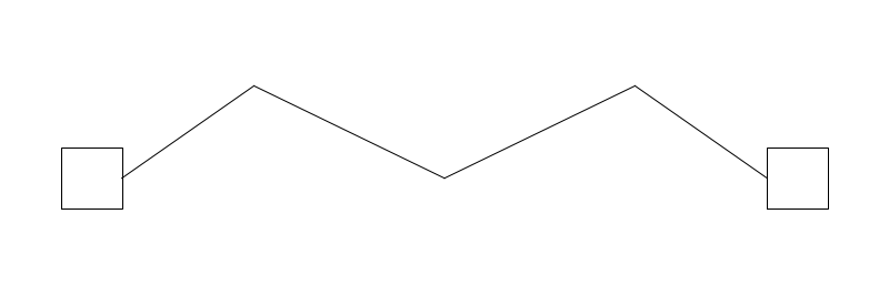
A folding closet set drawn with its panels in the stacked position: reach-in closets, laundry alcoves, and mechanical closet fronts in residential and light hospitality plans. The stacked panels are the reason the symbol exists, showing how much of the nominal opening is actually reachable and where the stack lands against adjacent trim or a return wall.
48in default is the common two-pair closet opening, and the 24-72in range runs from a single-pair 24in linen closet to a 72in reach-in. Folded panels park at each jamb, so usable opening is well under nominal width, which is why bifolds are rarely chosen where a specific clear width has to be held.
Insertion is the opening left jamb on the wall centerline. The block draws 57in wide against a 48in nominal opening, so it does not trim flush to the rough opening and needs trimming or a wall break sized to the opening rather than to the block. The 9.1in depth is the folded stack standing off the wall, and that is the dimension that collides with a nightstand or an in-swinging door.
Traded for door-pocket-32 whenever the panel projection into the room cannot be given up, since both solve the same problem of a closet opening with no room for a swing arc.
| Plan footprint (W x H) | 57in x 9.13in |
|---|---|
| Units | inches |
| DXF version | R2018 |
| Insertion datum | opening left jamb on wall centerline |
| Parameter | Default | Range / options |
|---|---|---|
| Width | 48in | 24in–72in |
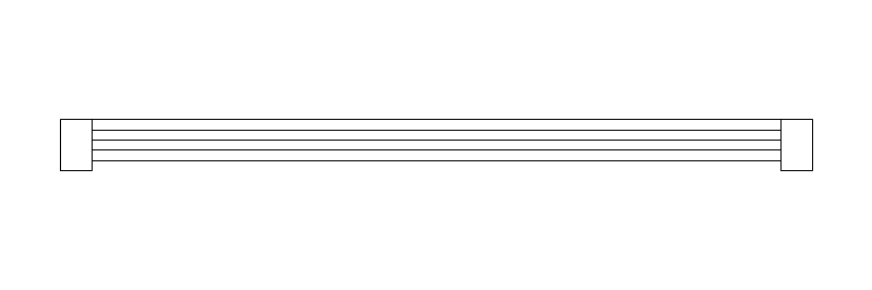
A sectional overhead door drawn closed on the garage wall of a residential plan. It appears mainly to fix the opening location, which in turn sets the driveway apron alignment and the header span above, and it is placed by residential designers working the same sheet as the floor plan.
108in (9ft) is the common single-car width, and the 96-192in range brackets the two sizes most stock sectional doors ship in: an 8ft single at the low end and a 16ft double at the top. Leaf height, conventionally 7 or 8ft, never appears in a plan symbol.
Datum is the left jamb inner face on the wall line, not the wall centerline the swing-door blocks use, with the door body developing toward -Y. The 118 x 8in footprint against a 108in nominal is jamb and vertical track, so each return wall gives up roughly 5in that a workbench or a hose bib cannot have.
Drawn with a personnel door such as door-swing-36 on the wall between garage and house, since the plan has to show both the vehicle opening and the way people actually move between the two spaces.
| Plan footprint (W x H) | 118in x 92in |
|---|---|
| Units | inches |
| DXF version | R2018 |
| Insertion datum | left jamb inner face on wall line (door to -Y) |
| Parameter | Default | Range / options |
|---|---|---|
| Width | 108in | 96in–216in |
| Height | 84in | 84in–168in |
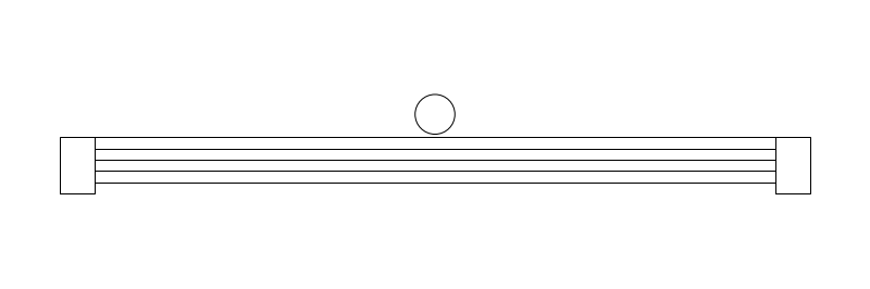
A coiling service door drawn in plan with its jambs and the coil at the head: loading dock openings, warehouse bays, shop and drive-through openings on industrial and tenant-improvement drawings. It is drawn closed, since the door stacks vertically and has no plan sweep to show.
120in (10ft) default suits a single dock or shop bay, and the 72-480in range runs from a small service opening to a 40ft drive-through. The jamb_depth parameter, 6-16in with a 10in default, is the guide and bracket projection off the wall, and that is the dimension that clashes with a bollard, a panelboard, or a conveyor.
Insertion is at the left jamb inner face with the coil drawn at the head, so the block references the finished opening and not a wall centerline. The 132 x 17.5in footprint puts 6in of guide at each side of a 120in opening. Rotate onto the wall; mirror only when the coil side and guide detail genuinely reverse.
Coordinated with guardrail at a raised dock edge and with the bollard line protecting the guides, both of which have to stop clear of the opening so the curtain can come all the way down.
| Plan footprint (W x H) | 132in x 34in |
|---|---|
| Units | inches |
| DXF version | R2018 |
| Insertion datum | left jamb inner face on wall line (curtain to -Y, coil at head) |
| Parameter | Default | Range / options |
|---|---|---|
| Width | 120in | 72in–480in |
| Jamb depth | 10in | 6in–16in |
| Height | 120in | 96in–240in |
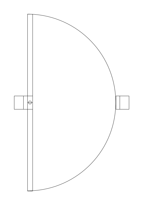
| Plan footprint (W x H) | 39in x 60in |
|---|---|
| Units | inches |
| DXF version | R2018 |
| Insertion datum | hinge point on wall centerline |
| Parameter | Default | Range / options |
|---|---|---|
| Width | 30in | 24in–48in |
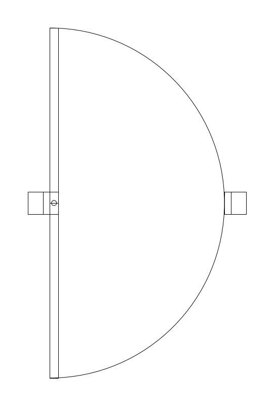
| Plan footprint (W x H) | 45in x 72in |
|---|---|
| Units | inches |
| DXF version | R2018 |
| Insertion datum | hinge point on wall centerline |
| Parameter | Default | Range / options |
|---|---|---|
| Width | 36in | 24in–48in |
| Plan footprint (W x H) | 51in x 84in |
|---|---|
| Units | inches |
| DXF version | R2018 |
| Insertion datum | hinge point on wall centerline |
| Parameter | Default | Range / options |
|---|---|---|
| Width | 42in | 24in–48in |
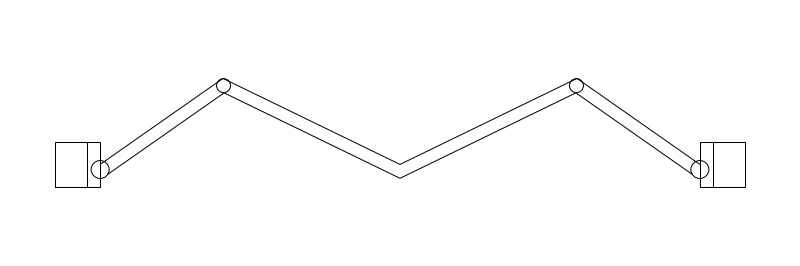
| Plan footprint (W x H) | 69in x 10.85in |
|---|---|
| Units | inches |
| DXF version | R2018 |
| Insertion datum | opening left jamb on wall centerline |
| Parameter | Default | Range / options |
|---|---|---|
| Width | 60in | 24in–96in |
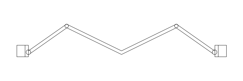
| Plan footprint (W x H) | 81in x 12.57in |
|---|---|
| Units | inches |
| DXF version | R2018 |
| Insertion datum | opening left jamb on wall centerline |
| Parameter | Default | Range / options |
|---|---|---|
| Width | 72in | 24in–96in |
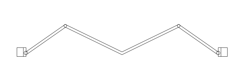
| Plan footprint (W x H) | 105in x 16.02in |
|---|---|
| Units | inches |
| DXF version | R2018 |
| Insertion datum | opening left jamb on wall centerline |
| Parameter | Default | Range / options |
|---|---|---|
| Width | 96in | 24in–96in |
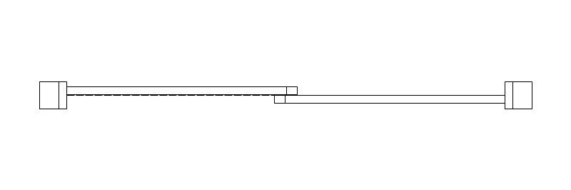
| Plan footprint (W x H) | 81in x 4.5in |
|---|---|
| Units | inches |
| DXF version | R2018 |
| Insertion datum | opening left jamb on wall centerline |
| Parameter | Default | Range / options |
|---|---|---|
| Width | 72in | 48in–96in |
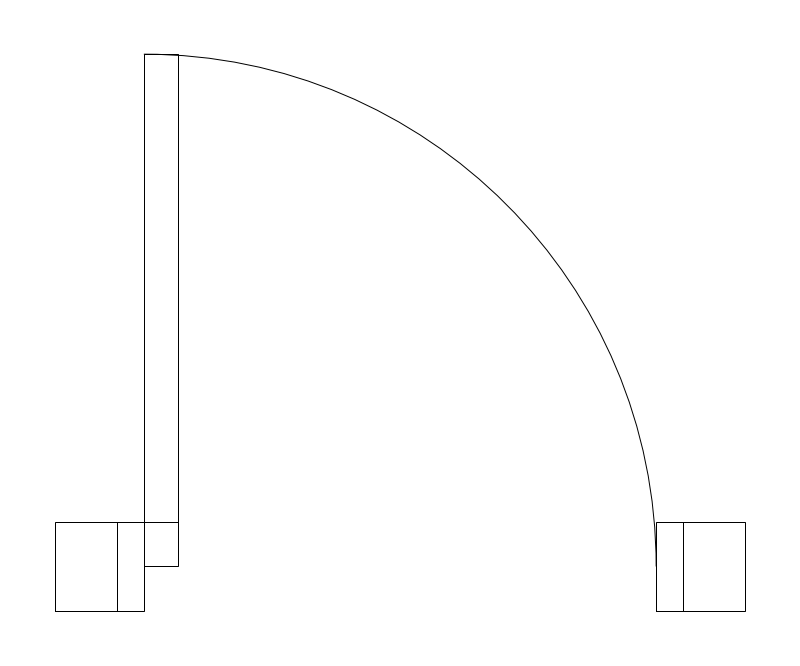
The narrow single leaf, and on a residential plan usually a closet, a linen cupboard or a utility door rather than a room door. It is below the width an accessible route can use, so where it appears on a route the schedule has to say why - which is the main thing a reviewer checks a 26in leaf for.
26in leaf, adjustable 24-48in across the swing-door range. A 26in leaf gives roughly 24in clear with the door open 90 degrees, short of the 32in minimum clear width an accessible door needs.
Insertion is the hinge point on the wall centerline, so the block lands on a wall snap and the hand and swing_out flags flip the leaf instead of forcing a mirror. The 35 x 28.2in footprint is mostly arc, so it selects far larger than the 26in opening it represents; keep it on A-DOOR.
Drawn on closets and utility openings alongside the wider leaves in the same run, where the door schedule carries all of them at once.
| Plan footprint (W x H) | 35in x 28.25in |
|---|---|
| Units | inches |
| DXF version | R2018 |
| Insertion datum | hinge point on wall centerline |
| Parameter | Default | Range / options |
|---|---|---|
| Width | 26in | 24in–48in |
| Hand | left | left / right |
| Swing direction | false | true / false |
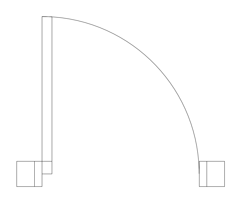
A secondary room or closet leaf, one size up from the 26in. Still below accessible clear width, so it goes on doors that serve a space rather than a route: a pantry, a linen closet, a small utility room.
28in leaf, adjustable 24-48in. About 26in clear with the door open 90 degrees.
Hinge point on the wall centerline, hand and swing_out flags rather than a mirror. The 37 x 30.2in footprint is arc, not opening; keep it on A-DOOR.
Used with the 26 and 30in leaves where a plan carries a mixed residential door schedule.
| Plan footprint (W x H) | 37in x 30.25in |
|---|---|
| Units | inches |
| DXF version | R2018 |
| Insertion datum | hinge point on wall centerline |
| Parameter | Default | Range / options |
|---|---|---|
| Width | 28in | 24in–48in |
| Hand | left | left / right |
| Swing direction | false | true / false |
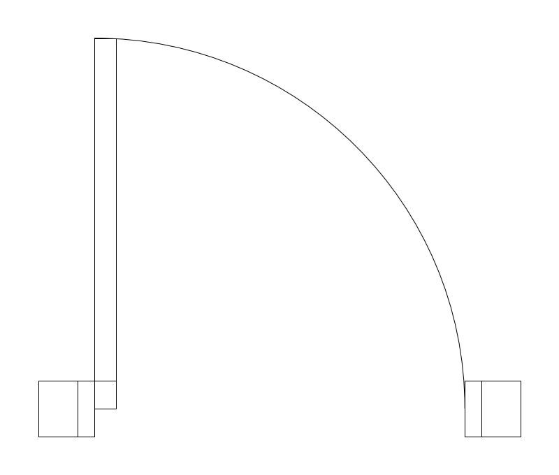
The common residential bedroom and bathroom leaf, and the smallest single swing that reads as a room door rather than a closet door on a plan. It is the width most often drawn where no accessible route passes, which makes it the one to check against the route diagram rather than against the room.
30in leaf, adjustable 24-48in. About 28in clear with the door open 90 degrees - short of the 32in an accessible door needs, which is why 32 and 36in leaves exist alongside it.
Hinge point on the wall centerline; the hand and swing_out flags flip the leaf. The 39 x 32.2in footprint is mostly arc. Keep it on A-DOOR, and check the arc against the fixture layout rather than against the wall - in a small bathroom the swing and the fixture clearances compete for the same floor.
Drawn on bedrooms and bathrooms, where the course also keeps a bathroom door from facing a bed and from facing the front door.
| Plan footprint (W x H) | 39in x 32.25in |
|---|---|
| Units | inches |
| DXF version | R2018 |
| Insertion datum | hinge point on wall centerline |
| Parameter | Default | Range / options |
|---|---|---|
| Width | 30in | 24in–48in |
| Hand | left | left / right |
| Swing direction | false | true / false |
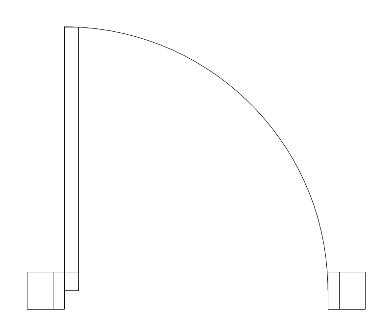
The narrowest leaf that can meet accessible clear width, and the one specified where a 36in leaf will not fit but the opening still has to be on a route. It leaves almost no margin, so the hardware and the stop are what decide whether it passes.
32in leaf, adjustable 24-48in. A 32in leaf gives roughly 30in clear with the door open 90 degrees once the leaf thickness and stop are taken off, so meeting the 32in clear minimum usually needs the leaf at 34 to 36in rather than 32in - which is the reason 36in is the usual accessible pick.
Hinge point on the wall centerline, hand and swing_out flags. The 41 x 34.2in footprint is arc. Keep it on A-DOOR and draw the maneuvering clearance separately where the sheet has to show it.
Checked against the same maneuvering clearance the 36in leaf takes, since the clearance is set by the approach rather than by the leaf width.
| Plan footprint (W x H) | 41in x 34.25in |
|---|---|
| Units | inches |
| DXF version | R2018 |
| Insertion datum | hinge point on wall centerline |
| Parameter | Default | Range / options |
|---|---|---|
| Width | 32in | 24in–48in |
| Hand | left | left / right |
| Swing direction | false | true / false |
Standards are listed for drafting context only. A symbol drawn to a convention is not a compliance determination - verify against the governing code and the specified product. See the license and terms.
Doors with real swing arcs for the plan you are laying out. Open one in the editor or take the DXF.
Every category, every MEP orientation, DXF R2018, sorted into folders. Tell us where to send it and the download starts immediately.
If nothing happened, click here to grab the ZIP.