Ten material-handling CAD blocks for the warehouse floor: 40x48 pallet, 48x40 IBC tote, a selective pallet-rack run and a single 96in bay, conveyor segment, platform scale, loading-dock leveler, an air compressor, a hand pallet jack and a counterbalance forklift drawn for aisle checking. The pallet and the rack bay are the two that set the aisle geometry, and everything else has to clear them. Free DXF downloads.
10 blocks, 10 downloads on this page. DXF R2018, drawn in inches. Free, no signup.
DWG (R2000, converted from the DXF). PNG is the plan-view preview.
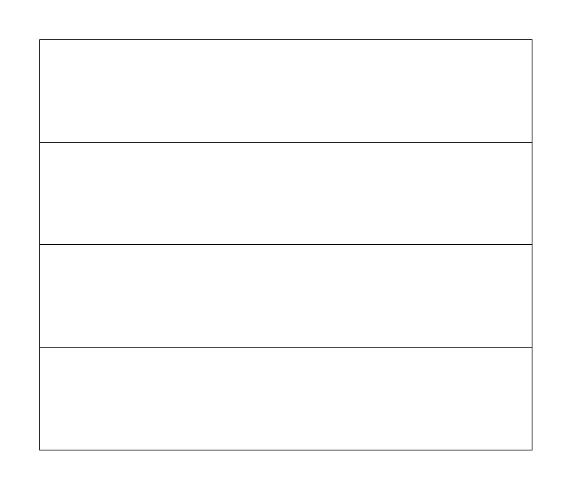
The GMA-footprint pallet most North American warehouse layouts are built around, standing for a unit load in a staging lane, a floor stack or a rack position. Nobody specifies a pallet, and yet aisle widths, bay sizes and dock staging depth all resolve back to this rectangle.
Locked at 48 x 40in because it is a standard rather than a design choice: 48in along the stringers, 40in across the deckboards. Orientation is the only variable. Stored 48in face out it is 40in deep, which is where the conventional 42in rack frame comes from.
The block draws three stringers and the deckboard notches at the fork entries, so a mirrored copy is indistinguishable and orientation matters only as a rectangle. Near-left corner insertion makes arraying trivial: step at pallet dimension plus whatever clearance the operation actually runs, not the nominal figure. Keep pallets on a layer you can freeze, since they are a study aid and not a construction item.
The rack bay is its counterpart, since bay width and frame depth both derive from how many of these fit an opening and which way they face. It is also the load a platform scale deck gets checked against.
| Plan footprint (W x H) | 48in x 40in |
|---|---|
| Units | inches |
| DXF version | R2018 |
| Insertion datum | near-left corner |
| Parameter | Default | Range / options |
|---|---|---|
| W | 48in | 48in–48in |
| D | 40in | 40in–40in |
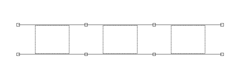
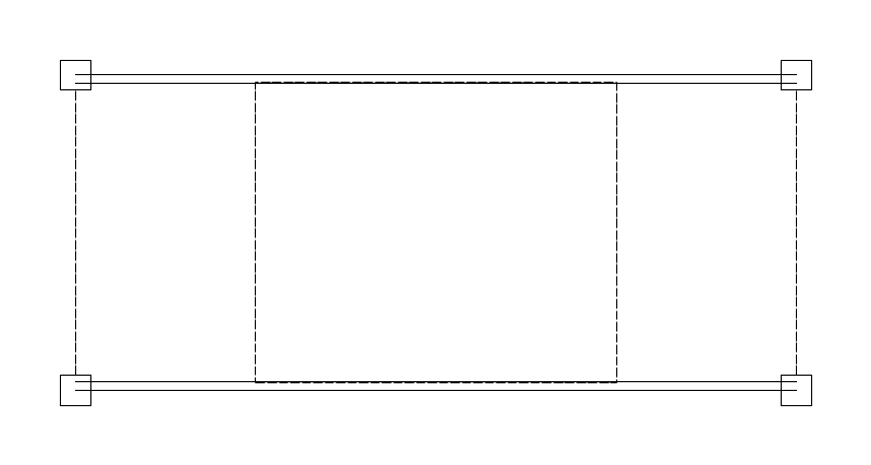
A run of selective pallet rack, drawn as upright frames with beams between and a dashed pallet position in each opening. This is the block that fills a distribution center plan, and placing it is a negotiation with sprinkler coverage above, lift-truck aisle widths, egress routes and a column grid it has to miss.
Depth 36-48in tracks upright frame depth, 42in being conventional for pallets stored 40in deep. The 292in default for three 96in bays is 288in of openings plus 4in upright posts reading 2in past each end, and the 46in extent is the 42in frame plus those same posts front and back.
Near-left upright corner insertion grows the run toward +X as bay count rises, so set bays and bay_w before placing it against the first column line. Each bay carries a single dashed 48 x 40in pallet as a placement hint, which is a drawing simplification, since a 96in opening is conventionally loaded with two 48in-face pallets; read it as a scale cue, not a load count. Keep rack on its own layer, because fire protection overlays it and will ask about flue spaces this symbol does not draw.
Sized directly off the pallet block, since bay width and frame depth both come from pallet dimensions and orientation. Everything else on the plan gets placed against the finished rack run rather than before it.
| Plan footprint (W x H) | 292in x 46in |
|---|---|
| Units | inches |
| DXF version | R2018 |
| Insertion datum | near-left upright corner (a run standing in a grid of rows and aisles, not against a wall) |
| Parameter | Default | Range / options |
|---|---|---|
| Bays | 3 | 1–10 |
| Bay width | 96in | 48in–144in |
| Depth | 42in | 36in–48in |
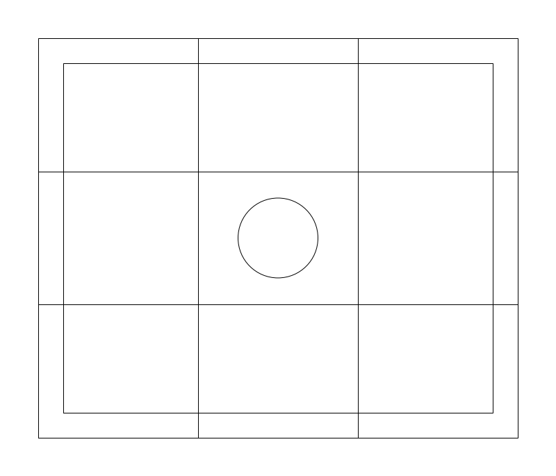
The caged intermediate bulk container that liquids arrive and move in, with 275 and 330 gallon units sharing this plan footprint and differing only in height. Layouts use it for staged chemical storage, batching areas and filling stations, so it appears in arrays and represents inventory rather than equipment.
Width and depth are locked at 48 x 40in on purpose: the tote's pallet base matches the North American pallet footprint, and letting it float would break the module that racking, dock doors and truck cube are all built on.
The discharge valve is drawn at the front (-Y) face, and that is what orients the tote. Rotate so the valve faces the aisle or the fill station an operator actually has to reach. Near-left corner insertion lines it up with the pallet block and with rack openings without offset math.
Interchangeable with the pallet wherever a layout shows staging. Where the contents are regulated, a containment curb and a floor drain or sump follow onto the same sheet.
| Plan footprint (W x H) | 48in x 40in |
|---|---|
| Units | inches |
| DXF version | R2018 |
| Insertion datum | near-left corner |
| Parameter | Default | Range / options |
|---|---|---|
| W | 48in | 48in–48in |
| D | 40in | 40in–40in |
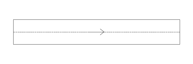
One straight run of belt or roller conveyor, the unit you repeat to build a line between workstations and out to a palletizer. The architect needs it as much as the industrial engineer, because a conveyor crossing an aisle is an obstruction that has to be resolved with a gate, a lift section or a crossover.
Width 12-48in covers standard belt and roller widths, with carton handling around 18 to 24in and pallet conveyor above that. Length is the parameter doing the work: 24 to 480in per segment covers a two-foot transfer and a forty-foot run, and the roller tick count scales with length so the segment keeps reading as conveyor at either extreme.
Near-left corner insertion with the belt running +X makes chaining straightforward: insert, set length, start the next at the end point of the last. Curves, merges and transfers are not in this block, so leave a gap at every direction change and detail it. The travel arrow at midspan is the only asymmetric feature, so check it after any mirror.
Carries the pallet and tote blocks that stand for whatever rides on it, and runs past rack bays where the layout is a pick line. Where it passes beneath a mezzanine it is competing for headroom, and the conveyor elevation usually loses that argument.
| Plan footprint (W x H) | 120in x 18in |
|---|---|
| Units | inches |
| DXF version | R2018 |
| Insertion datum | near-left corner (belt runs +X) |
| Parameter | Default | Range / options |
|---|---|---|
| Width | 18in | 12in–48in |
| Length | 120in | 24in–480in |
A low-profile floor scale for weighing pallets, drums and totes at shipping and receiving, in batching areas and at waste-out points. Recessed into a pit or surface-mounted with ramps, it is one of the few equipment blocks with a structural consequence.
The 48 x 48in default is the common four-foot deck. A 48 x 40in pallet lands on it flush in the 48in direction with roughly 8in spare in the other, so there is no margin all round; if the operation needs clearance on every side, step the deck up toward the 96in maximum. Capacity and division size are schedule items and do not follow from the footprint.
The block draws the weigh deck floating inside an outer frame with a load cell at each corner, and it is the deck perimeter you dimension the pit opening or the ramp toe from, not the center. On a surface-mounted scale the ramps fall entirely outside these extents and have to be drawn separately.
Drawn with the pallet or the IBC tote laid over it to prove the deck accepts the unit load, and set into the traffic path it interrupts rather than tucked off to one side.
| Plan footprint (W x H) | 48in x 48in |
|---|---|
| Units | inches |
| DXF version | R2018 |
| Insertion datum | near-left corner |
| Parameter | Default | Range / options |
|---|---|---|
| Width | 48in | 36in–96in |
| Depth | 48in | 36in–96in |
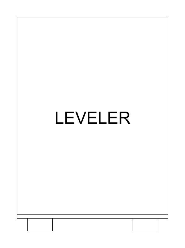
Pit-style dock leveler at a loading dock face, drawn on warehouse and industrial plans. The pit is a formed opening in the dock slab, so the block has to coordinate with the dock face, the bumpers, and the structural edge angle.
Default 72in wide x 96in deep. Width runs 66-84in and depth 72-120in. A 6ft width serves standard trailers; 7ft eases forklift approach angles. Deeper decks flatten the working grade when the trailer bed sits well below dock height.
The datum is the near-left pit corner at the dock face, so it aligns to the exterior wall line and repeats at overhead-door spacing. The 102in bbox runs 6in past the nominal 96in pit depth.
Drawn with bollards guarding the dock apron and with the overhead door openings above each pit.
| Plan footprint (W x H) | 72in x 102in |
|---|---|
| Units | inches |
| DXF version | R2018 |
| Insertion datum | near-left corner of pit at dock face (a pit set into the slab, not against a wall) |
| Parameter | Default | Range / options |
|---|---|---|
| Width | 72in | 66in–84in |
| Depth | 96in | 72in–120in |
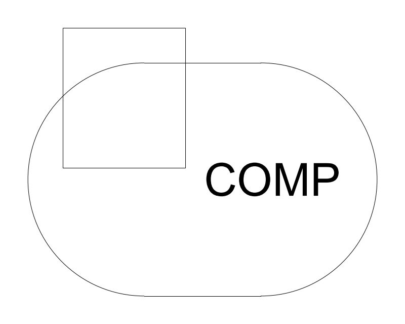
The packaged shop compressor at the head of a plant compressed-air system, sitting in a compressor room or a shop corner with the dryer and filters. It matters to two sheets at once: a large connected load on the electrical plan, and the origin of the air header on the piping plan.
This is a tank-mounted unit, a horizontal receiver with the pump, motor and belt guard sitting on it, so depth is the receiver and the motor package overhangs it to the rear at 1.15 times depth. That is why a 36 x 24in default publishes a 36 x 27.6in footprint. Toward the top of the width range the machine is arriving as an integrated skid, and its real footprint comes off the vendor drawing rather than out of this block.
Corner insertion snaps to the wall or column line you set equipment against and rotates about that corner. Rotation is meaningful here: the motor package sits on the rear face and the discharge nozzle is on the receiver to one side, so offset clearance for the control-panel side and for the cooling-air inlet rather than pushing either into a wall.
The receiver is already part of this block, so reach for the horizontal tank only where the design has a separate wet or dry receiver downstream. What does belong beside it is a floor drain, because the aftercooler and the receiver both make condensate that has to go somewhere.
| Plan footprint (W x H) | 36in x 24in |
|---|---|
| Units | inches |
| DXF version | R2018 |
| Insertion datum | near-left corner |
| Parameter | Default | Range / options |
|---|---|---|
| Width | 36in | 24in–72in |
| Depth | 24in | 18in–36in |
| Plan footprint (W x H) | 100in x 46in |
|---|---|
| Units | inches |
| DXF version | R2018 |
| Insertion datum | near-left upright corner (single 96 in bay) |
| Parameter | Default | Range / options |
|---|---|---|
| Bays | 1 | 1–10 |
| Bay width | 96in | 48in–144in |
| Depth | 42in | 36in–48in |
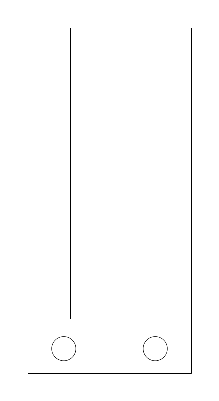
| Plan footprint (W x H) | 27in x 57in |
|---|---|
| Units | inches |
| DXF version | R2018 |
| Insertion datum | near-left corner of the fork footprint (handle projects -Y, dashed) |
| Parameter | Default | Range / options |
|---|---|---|
| Length | 48in | 42in–54in |
| Width | 27in | 20in–27in |
| Handle | 20in | 12in–30in |
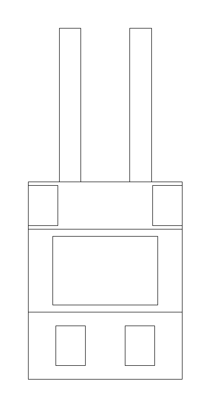
| Plan footprint (W x H) | 42in x 96in |
|---|---|
| Units | inches |
| DXF version | R2018 |
| Insertion datum | near-left corner of the body (forks project +Y) |
| Parameter | Default | Range / options |
|---|---|---|
| Length | 96in | 72in–144in |
| Width | 42in | 36in–54in |
| Fork Len | 42in | 36in–48in |
Standards are listed for drafting context only. A symbol drawn to a convention is not a compliance determination - verify against the governing code and the specified product. See the license and terms.
Pallets, racking and dock equipment for the plant layout. Open one in the editor or take the DXF.
Every category, every MEP orientation, DXF R2018, sorted into folders. Tell us where to send it and the download starts immediately.
If nothing happened, click here to grab the ZIP.