Seven HVAC equipment CAD blocks: boiler, chiller, furnace, air handler, AC condenser, thermostat and a 48in fume hood. These are the pieces the duct connects to, and their footprints - up to 48x96in for the chiller - are what a mechanical room has to be sized around. Free DXF downloads drawn to scale in inches.
7 blocks, 7 downloads on this page. DXF R2018, drawn in inches. Free, no signup.
DWG (R2000, converted from the DXF). PNG is the plan-view preview.
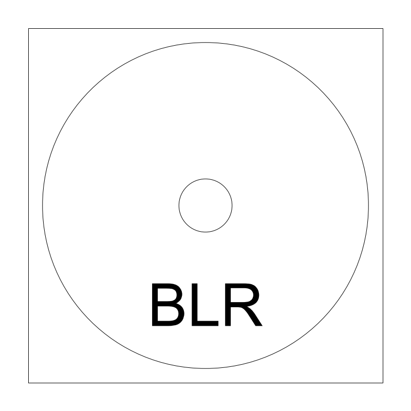
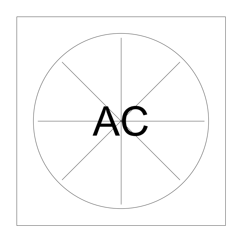
Outdoor condensing unit on its pad, drawn on residential and light commercial site and mechanical plans. Placement is driven by side-yard setbacks, line-set run length to the indoor coil, and noise relative to bedroom windows.
The 30in square default is a mid-range residential unit. Cabinet size tracks coil face area, which grows with capacity, so the 24-42in range runs from a small residential condenser up through large residential and light commercial cabinets. Do not read tonnage off the footprint - match the actual selected unit. Manufacturer service clearance around the cabinet usually governs the pad location, not the cabinet dimension itself.
The datum is the near-left corner of the pad, so the block sets to the pad corner offset from the foundation face. It appears on both the site plan and the mechanical plan, typically on different layers in each.
Drawn as a matched set with the air handler or furnace it serves indoors, with the line set routed between them.
| Plan footprint (W x H) | 30in x 30in |
|---|---|
| Units | inches |
| DXF version | R2018 |
| Insertion datum | near-left corner of pad |
| Parameter | Default | Range / options |
|---|---|---|
| Size | 30in | 24in–42in |
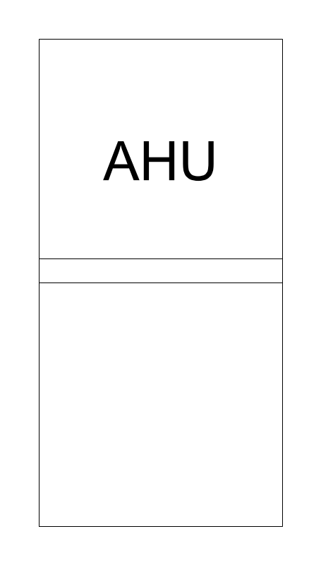
Indoor fan coil or air handler in a closet, attic platform, or mechanical room. Mechanical drafters place it to set the supply plenum takeoff and the return drop, and to reserve service access at the coil and blower panels.
Default 24in wide x 48in deep; width adjusts 18-36in and depth 30-72in. Cabinet width tracks nominal capacity, while depth grows with an added coil section, a filter rack, or an auxiliary heat module stacked into the same cabinet.
Near-left corner datum. Configuration matters more than the outline here - upflow, downflow, and horizontal arrangements present different plenum faces, so annotate airflow direction rather than expecting the plan rectangle to convey it.
Drawn as the indoor half of a split system with the AC condenser outdoors, and connected to the supply and return trunk ducts.
| Plan footprint (W x H) | 24in x 48in |
|---|---|
| Units | inches |
| DXF version | R2018 |
| Insertion datum | near-left corner |
| Parameter | Default | Range / options |
|---|---|---|
| Width | 24in | 18in–36in |
| Depth | 48in | 30in–72in |
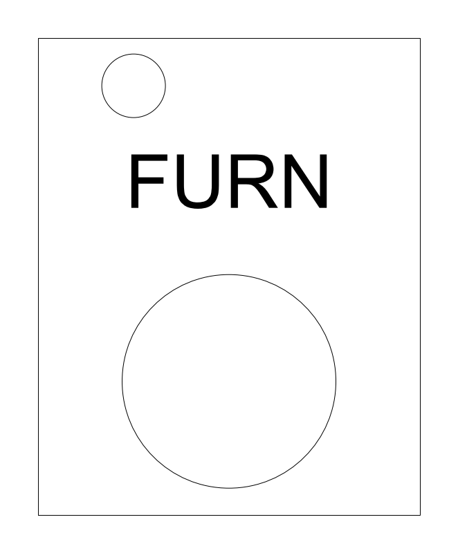
Gas furnace in a mechanical closet, basement, or attic. Drafters locate it to coordinate the flue or vent penetration, the gas line, and the return drop, plus service clearance at the burner access panel.
Default 24in wide, adjustable 17-28in - the standard family of furnace cabinet widths, which step with input BTU and blower size. Depth defaults to 30in and only moves within 28-34in, because cabinet depth is largely standardized regardless of capacity.
The near-left corner is the datum. The plan rectangle is only the cabinet - vent routing, combustion air openings, and clearances to combustibles come from the appliance listing and belong in notes, not in the block outline.
Drawn with an evaporator coil section above it in a split system, and matched to the AC condenser sited outdoors.
| Plan footprint (W x H) | 24in x 30in |
|---|---|
| Units | inches |
| DXF version | R2018 |
| Insertion datum | near-left corner |
| Parameter | Default | Range / options |
|---|---|---|
| Width | 24in | 17in–28in |
| Depth | 30in | 28in–34in |

Wall-mounted control device for residential and light commercial electrical and mechanical plans. Placement matters more than for most wall devices - it is kept off exterior walls, away from supply diffusers, and out of direct sun, since all three bias the sensed temperature.
The parameter is a radius, not a diameter: the 4in default plots an 8in circle, and the 2-8in radius range plots a 4in to 16in symbol. This is a symbol scale rather than a product dimension - an actual thermostat is only a few inches across, so pick a radius that reads at your plot scale instead of one that models the device.
The datum is the wall-mount point on the wall line, so the block snaps to the wall face and the symbol projects into the room. Usually tagged T or T-1 and keyed to the zone or air handler it controls.
Drawn as the control point for the furnace or air handler, and placed with other wall devices on the electrical plan.
| Plan footprint (W x H) | 8in x 8in |
|---|---|
| Units | inches |
| DXF version | R2018 |
| Insertion datum | wall-mount point on wall line |
| Parameter | Default | Range / options |
|---|---|---|
| Radius | 4in | 2in–8in |
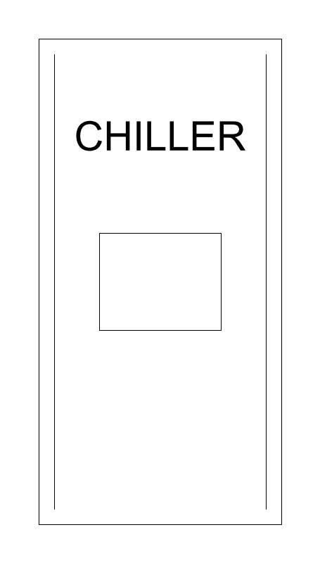
The packaged air-cooled chiller: a skid with a finned condenser coil bank down each long side, a compressor block mid-skid and a condenser fan ring at each end. It lands on a roof, a pad or a mechanical yard rather than in a plant room, and it is usually the largest single connected load on the electrical sheet.
Width 36-96in is the skid measured across the two coil banks. Depth 60-144in is where machine size actually shows, since capacity is added by lengthening coil and adding fans. The block draws two fan rings at any depth, so at the top of the range read the fan count as schematic and take the real arrangement off the selection.
Near-left corner insertion sets it against a curb line or pad edge and lines several machines up on a common face. Rotation decides which way the unit breathes, since both coil faces are on the long sides; a coil pushed up against a parapet, a wall or the next machine is the recirculation problem that surfaces later as a capacity complaint. Draw the manufacturer's airflow clearance off each coil face as a dashed band so the architect sees it when placing screens and walls.
Read against the air compressor: the two big skid-mounted packages, each with its own feeder, that a service size gets checked against. Substituting a water-cooled machine changes the drawing entirely, adding two water loops and a tube-pull zone roughly the length of the shell.
| Plan footprint (W x H) | 48in x 96in |
|---|---|
| Units | inches |
| DXF version | R2018 |
| Insertion datum | near-left corner |
| Parameter | Default | Range / options |
|---|---|---|
| Width | 48in | 36in–96in |
| Depth | 96in | 60in–144in |
The heat source in a hydronic or steam mechanical room, drawn as a round pressure vessel seated in a square base curb with a burner stub at the front. That is the vertical package read; a cast-iron sectional or a wall-hung condensing unit has a different footprint and should not borrow this symbol.
dia drives both the vessel and the square curb it sits in, so the plotted footprint is dia x dia, 36 x 36in at the default, with the shell circle a little inboard of the square. What the footprint does not include is service space, which is the number that actually sizes the room.
The burner and fuel-train stub is drawn on the front (-Y) face, so rotation carries information: it marks the side the gas train, controls and burner access live on. Insertion at the near-left corner of the square rather than at the shell center lets it snap to a grid line the way rectangular equipment does. Breeching, gas train and relief piping are drawn as separate lines; the block is the shell and its curb.
The floor drain near it is what receives relief-valve discharge and blowdown, so it goes on the plan at the same time rather than after the piping is routed. In a four-pipe plant the chiller is the other half of the system, but it is usually outdoors while this sits in a room.
| Plan footprint (W x H) | 36in x 36in |
|---|---|
| Units | inches |
| DXF version | R2018 |
| Insertion datum | near-left corner of footprint |
| Parameter | Default | Range / options |
|---|---|---|
| Diameter | 36in | 24in–72in |
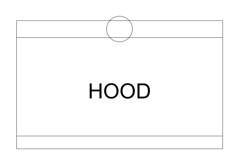
Overhead exhaust hood shown in plan above a cooking surface. The symbol carries a baffle line and a duct collar at the back so the exhaust takeoff reads at plan scale. Because it sits above the counter plane it is conventionally drawn dashed or in a lighter weight, and it drives a roof or exterior wall exhaust penetration.
Default 48in wide, adjustable 36-72in, with depth 24-36in matching counter depth. The 31in bbox runs 1in past the 30in default depth for the shell. Common practice is a hood at least as wide as the appliance below it and often extending past each side, so a 30in range takes a 30-36in hood and a 48in range a 48in-plus hood.
The back-center wall-line datum matches the cooktop datum exactly, so the two stack concentrically at the same insertion point. Keep it off the casework layer since it is an overhead element, not a counter object.
Drawn directly over the cooktop block, which shares its datum and drives its width.
| Plan footprint (W x H) | 48in x 30in |
|---|---|
| Units | inches |
| DXF version | R2018 |
| Insertion datum | back-center on wall line |
| Parameter | Default | Range / options |
|---|---|---|
| Width | 48in | 36in–72in |
| Depth | 30in | 24in–36in |
Standards are listed for drafting context only. A symbol drawn to a convention is not a compliance determination - verify against the governing code and the specified product. See the license and terms.
Equipment blocks for the mechanical room and plant layout. Open one in the editor or take the DXF.
Every category, every MEP orientation, DXF R2018, sorted into folders. Tell us where to send it and the download starts immediately.
If nothing happened, click here to grab the ZIP.