Fence, gate, retaining wall, storage shed, mailbox and bike rack - six site CAD blocks that define a property's edges and the small structures along them. The fence and retaining wall are linear and get arrayed along a run; the shed, mailbox and rack are single placements. All are free DXF downloads.
6 blocks, 6 downloads on this page. DXF R2018, drawn in inches. Free, no signup.
DWG (R2000, converted from the DXF). PNG is the plan-view preview.
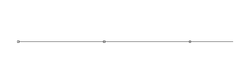
Straight fence run with post ticks, for property lines, yard enclosures, and screened equipment yards on site plans. Its purpose on the sheet is showing enclosure extents and where gates interrupt the run.
Default 240in (20ft), adjustable 24-2400in - from a 2ft screen return to a 200ft property side in a single insert. The posts toggle switches individual post symbols off, which is the right call on a long boundary run or a schematic where post ticks would clutter the plot.
It starts at the near-left end and runs +X, so lay it out from a corner monument or building corner and rotate each segment onto its property bearing. At 2in of bbox depth it plots as a line weight rather than an area - do not hatch it.
Broken by the gate block wherever access is needed, and stepped against the retaining wall where the grade changes.
| Plan footprint (W x H) | 241in x 2in |
|---|---|
| Units | inches |
| DXF version | R2018 |
| Insertion datum | near-left (start), runs +X |
| Parameter | Default | Range / options |
|---|---|---|
| Length | 240in | 24in–2400in |
| Posts | true | true / false |
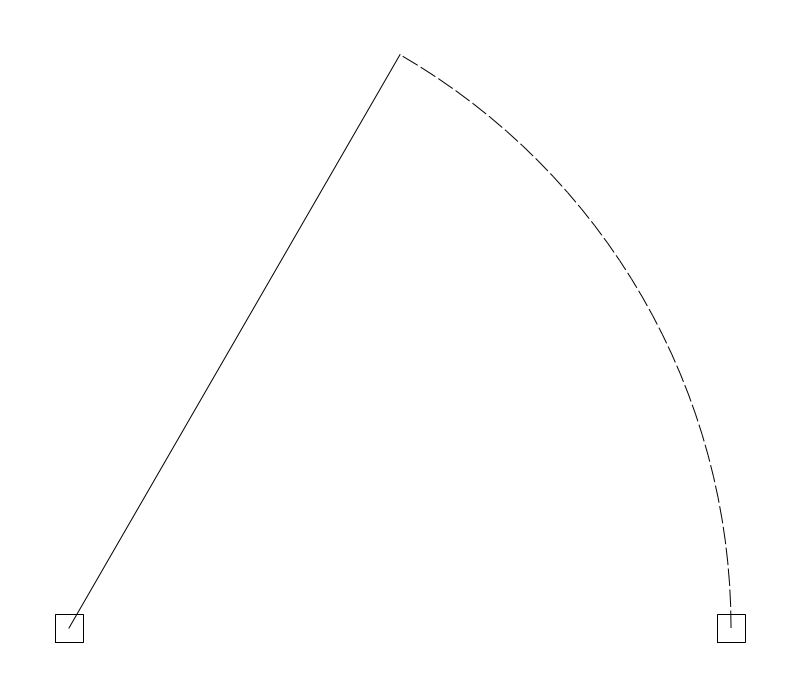
Swing gate with the leaf sweep shown, inserted where a fence run breaks for a walk or drive. The arc is the working part of the symbol - it proves the leaf clears a walk, a slope, or a parked car.
Default 48in, adjustable 36-144in, which spans a pedestrian walk gate up to a double drive gate. Past roughly five feet of leaf, a single swing gets heavy on its hinges and is commonly split into a pair rather than drawn as one panel.
The hinge post on the fence line is the datum, so mirroring the block flips the swing hand without relocating the hinge. The 50in bbox width carries 2in past the 48in leaf for the hinge and latch posts, and the 42.6in Y extent is swept arc geometry, not a physical footprint - never carry a dimension off it.
Drawn into the fence run it interrupts, and at pool enclosures where the barrier gate is a code-scoped element.
| Plan footprint (W x H) | 50in x 42.57in |
|---|---|
| Units | inches |
| DXF version | R2018 |
| Insertion datum | hinge post (near-left) on fence line |
| Parameter | Default | Range / options |
|---|---|---|
| Width | 48in | 36in–144in |
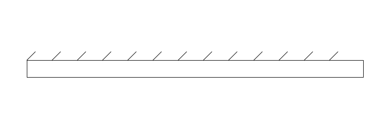
Wall in plan holding a grade change - terraced yards, driveway cuts, planter walls. Civil and landscape drafters draw it to carry top-of-wall and bottom-of-wall elevations that the structural sheet keys off. Jurisdictions commonly set an unbalanced-fill height above which an engineered design is required.
Default 240in (20ft) long, 12in thick; length adjusts 48-2400in and thickness 8-36in. Thickness tracks the wall system - roughly 8in for a small segmental block unit, 36in for a mass-gravity section or a cantilever stem drawn with batter.
The near-left corner is the datum with the wall running +X, so segments chain end to end for stepped and terraced runs. The 18in bbox depth exceeds the 12in thickness, meaning the block carries 6in of geometry behind the wall face.
Drawn with a fence along the top of wall and with the deck or patio the wall is holding up.
| Plan footprint (W x H) | 240in x 18in |
|---|---|
| Units | inches |
| DXF version | R2018 |
| Insertion datum | near-left corner (runs +X) |
| Parameter | Default | Range / options |
|---|---|---|
| Length | 240in | 48in–2400in |
| Thickness | 12in | 8in–36in |
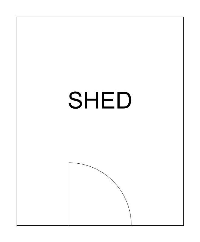
Detached accessory storage structure on residential site plans. It is drawn primarily to test setback compliance and lot coverage, since a shed is often the thing that pushes a small lot past its accessory-structure allowance.
Default 96in x 120in, a common 8ft x 10ft prefab. Both dimensions adjust 48-240in, covering a 4ft lean-to up to a 20ft x 20ft outbuilding. Two hundred square feet is the figure the model residential code uses for its permit exemption - the 80sf default sits well under it, the 400sf maximum well over.
Near-left corner datum. Setback dimensions run straight from the block edge to the property line, but the outline is the wall footprint with no eave projection, and setbacks are frequently measured to the eave - add that overhang separately if the reviewer measures it that way.
Drawn with the fence enclosing the rear yard and with the driveway or a walk providing the access path to it.
| Plan footprint (W x H) | 96in x 120in |
|---|---|
| Units | inches |
| DXF version | R2018 |
| Insertion datum | near-left corner |
| Parameter | Default | Range / options |
|---|---|---|
| Width | 96in | 48in–240in |
| Depth | 120in | 48in–240in |
Curbside post-mounted box for residential plot and landscape plans, set at the driveway and curb interface. It gets drawn mostly to keep the box clear of a driveway flare, a street tree, or a utility pedestal.
Default 12in diameter with a 7.2in bbox depth for the box body on its post; the 8-18in range runs from a small standard box to an oversized or locking parcel box. Postal service placement guidance, not the box size, usually sets where it lands.
Post center is the datum, so it snaps to a station offset from the curb face. At 1in=20ft a 12in box plots at about a twentieth of an inch on the sheet, so it normally takes a leader note rather than a dimension string.
Drawn beside the driveway apron and the sidewalk, since all three compete for the same few feet of parkway.
| Plan footprint (W x H) | 12in x 7.2in |
|---|---|
| Units | inches |
| DXF version | R2018 |
| Insertion datum | post center |
| Parameter | Default | Range / options |
|---|---|---|
| Diameter | 12in | 8in–18in |
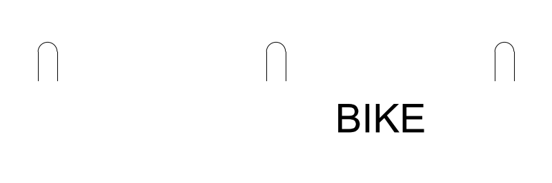
Loop-style bicycle rack shown in plan on site plans and ground-floor architectural plans. Landscape architects and site designers place it near building entries, transit plazas, and interior bike rooms, usually to satisfy a zoning bicycle-parking count.
The default three loops at 24in spacing produce a 50in run in a 6.5in-deep band. Spacing adjusts 18-36in and loops 1-10, so a single insert covers a two-bike entry rack or a ten-loop bank. APBP guidance puts rack elements on roughly 30in centers where two bikes are meant to share one element; the 18in end of the range packs elements tighter and in practice yields one bike each.
The near-left base datum seats the block against a curb line or wall face and lets it array cleanly along +X at whatever spacing the plan calls out. Site-furnishings layer, typically plotted at 1/8in or 1in=20ft.
Drawn alongside bollards and sidewalk runs, since bike parking nearly always lands on a paved walk edge that needs protection from vehicle overrun.
| Plan footprint (W x H) | 50in x 4in |
|---|---|
| Units | inches |
| DXF version | R2018 |
| Insertion datum | near-left base |
| Parameter | Default | Range / options |
|---|---|---|
| Loops | 3 | 1–10 |
| Spacing | 24in | 18in–36in |
Standards are listed for drafting context only. A symbol drawn to a convention is not a compliance determination - verify against the governing code and the specified product. See the license and terms.
Fencing, walls and the small structures along them. Open one in the editor or take the DXF.
Every category, every MEP orientation, DXF R2018, sorted into folders. Tell us where to send it and the download starts immediately.
If nothing happened, click here to grab the ZIP.