Two storage tank CAD blocks: a vertical tank shown as a 52in circle in plan and a horizontal tank at 144x48in. Which one appears is a footprint decision - the vertical costs floor area in one dimension, the horizontal in the other, and the tank farm layout follows from it. Both are free DXF downloads drawn to scale in inches.
2 blocks, 2 downloads on this page. DXF R2018, drawn in inches. Free, no signup.
DWG (R2000, converted from the DXF). PNG is the plan-view preview.
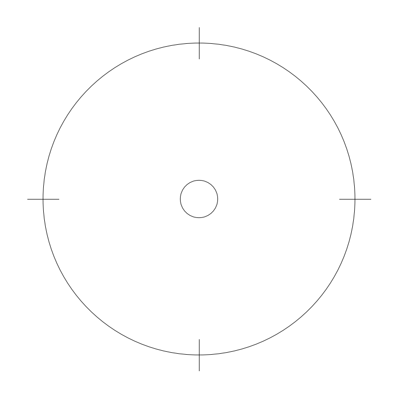
An upright cylindrical tank seen from above: shell circle with an inner plate line, a manway offset off center, four shell nozzles on the diagonals and quarter ticks at the shell. Used for process vessels, day tanks and chemical storage where floor area is the constraint and height is the answer.
Diameter runs 24-144in, and the plotted extents sit ten percent wider than the shell, 52.8in for a 48in tank, because the four quarter ticks read past it. That overrun is annotation rather than steel: reason about capacity from the shell circle and use the extents only to confirm the ticks are not colliding with something.
Center insertion is what you dimension to and what a radial clearance works from; one OFFSET of the shell circle gives the maintenance envelope. The manway is drawn off center deliberately, so rotation is worth setting on purpose wherever access matters. In a containment area draw the curb as a separate polyline sized from volume, since scaling this block up gives you a bigger tank, not a dike.
Commonly drawn in a row of identical tanks served by one floor drain or sump. A horizontal tank sitting next to one usually signals a different service rather than more of the same.
| Plan footprint (W x H) | 52.8in x 52.8in |
|---|---|
| Units | inches |
| DXF version | R2018 |
| Insertion datum | tank center |
| Parameter | Default | Range / options |
|---|---|---|
| Diameter | 48in | 24in–144in |
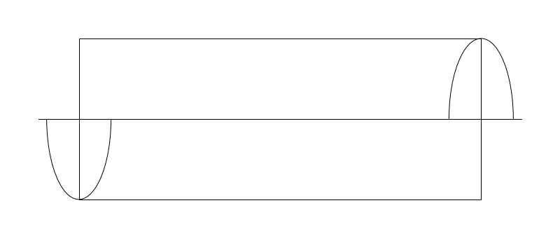
A cylindrical tank lying on saddles: fuel, process liquid, an air receiver, condensate. In plan the block draws the shell rectangle with dished heads seated inside it, a pair of saddle marks across the shell, three top nozzles and a centerline. Regulated contents pull a containment curb, a fill point and a vent onto the same drawing.
The drawn shell is exactly length by diameter, 120 x 48in at defaults. The published 144in extent is the centerline running a quarter-diameter past each end, not tank, since the heads are drawn inside the rectangle rather than added to it. Dimension clearances to the shell rectangle and treat the extra 24in as annotation.
Tank-center insertion suits how these get placed: centered on a pad or between saddle piers, then rotated to the pipe run. The two saddle marks across the shell are schematic. If the structural sheet needs real saddle locations, dimension them separately, because their spacing is an engineering result rather than a fixed fraction of shell length.
Sits downstream of a compressor where it is serving as a receiver, and beside the vertical tank where a height limit is what drove the orientation choice in the first place.
| Plan footprint (W x H) | 144in x 48in |
|---|---|
| Units | inches |
| DXF version | R2018 |
| Insertion datum | tank center |
| Parameter | Default | Range / options |
|---|---|---|
| Diameter | 48in | 24in–120in |
| Length | 120in | 48in–360in |
Standards are listed for drafting context only. A symbol drawn to a convention is not a compliance determination - verify against the governing code and the specified product. See the license and terms.
Vertical and horizontal vessels for the plant layout. Open one in the editor or take the DXF.
Every category, every MEP orientation, DXF R2018, sorted into folders. Tell us where to send it and the download starts immediately.
If nothing happened, click here to grab the ZIP.