Twenty-two fire-sprinkler pipe CAD blocks across eight fittings: 45 and 90-degree elbows, tee, cross, cap, reducer, straight run and riser. Elbows, tees and caps carry their compass orientations; the run and reducer come horizontal and vertical. Single-line schematic, which is how sprinkler pipe is drawn on a plan, and every one is a DXF download.
8 blocks, 22 downloads on this page. DXF R2018, drawn in inches. Free, no signup.
DWG (R2000, converted from the DXF). PNG is the plan-view preview.
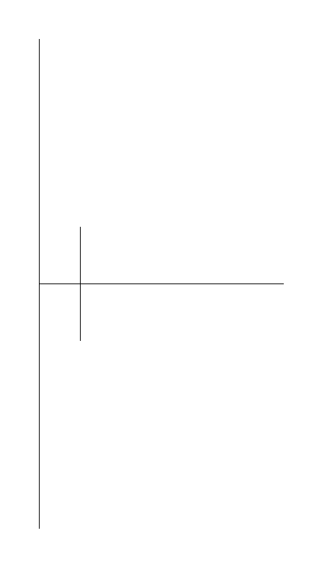
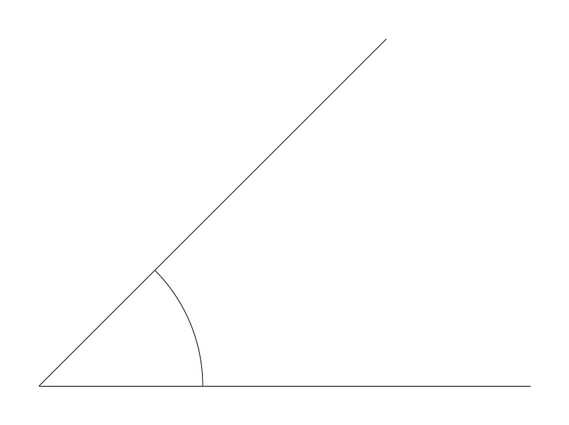
The shallow turn, used in pairs to walk a main past an obstruction without paying for two square corners. On a calculated system that is the whole argument for it: at 2in a 45 is worth about 2ft of equivalent pipe against roughly 5ft for a standard 90.
u, 6 to 96in, drives both legs - one on the axis, one at 45 degrees into the orient quadrant - so the default plots 12 x 8.485in, the height being 12 times sin 45. The arc across the corner stays at 4in however far u grows. Worth remembering that the two 45s plus the piece between them run longer than the square turn they replace, so part of the equivalent-length saving goes straight back into pipe, hangers and labor.
The vertex sits at origin rather than the arc center, matching how a piping designer dimensions to the theoretical intersection of the two centerlines. Orient names the quadrant the 45 leg swings into. Because that leg leaves the orthogonal grid, downstream fittings will not snap clean - build the offset as 45, run, 45 and let the run block absorb the odd dimension.
Rarely appears alone; it comes in pairs with a run between them forming the offset. The 90 is what it trades against, and in a tight ceiling the 45 pair usually loses on space rather than on hydraulics.
| Plan footprint (W x H) | 12in x 8.49in |
|---|---|
| Units | inches |
| DXF version | R2018 |
| Insertion datum | bend vertex (0,0); axis leg + 45deg leg into orient quadrant |
| Parameter | Default | Range / options |
|---|---|---|
| Orientation | NE | NE / NW / SE / SW |
| Nominal size | 12in | 6in–96in |
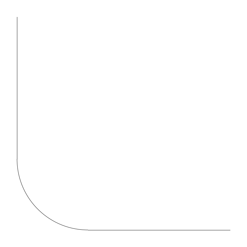
A square change of direction on a branch line, armover or cross main. Nothing is free in a calculated system: each 90 gets charged to the hydraulics as a length of equivalent pipe, so a route that turns four times dodging ductwork can push remote-area demand off the available supply curve.
u sets both legs, 6 to 96in, with ports at u along the two orient directions - a 12 x 12in square at default. The corner arc is a hard-coded 4in fillet that does not scale with u, so at u=96 it is a small nick on a very long corner. Read it as a fitting mark and not a bend radius; sprinkler steel is fitted, not bent. Real cost scales with diameter instead, roughly 5ft equivalent for a 2in standard elbow and 10ft at 4in.
Bend vertex at origin puts the block on the intersection of two centerlines, and both legs reach the same grid the runs and tees use. Pick the orient variant rather than rotating an insert, or the block name and the geometry stop agreeing in a fitting count. A long-turn 90 is charged far less than a standard one, and this symbol shows neither, so the difference has to reach the schedule.
Drops between run blocks wherever a main steps around a beam pocket or a duct. Weighed against a pair of 45s, which cost less in equivalent length but more in real pipe and usually one more hanger.
| Plan footprint (W x H) | 12in x 12in |
|---|---|
| Units | inches |
| DXF version | R2018 |
| Insertion datum | bend vertex (0,0); two ports at u along the two orient dirs |
| Parameter | Default | Range / options |
|---|---|---|
| Orientation | NE | NE / NW / SE / SW |
| Nominal size | 12in | 6in–96in |
The takeoff where a branch line leaves the cross main. Hydraulically this is the node that carries the sheet: flow splits here, and every head out on that branch gets balanced against whatever pressure the calculation finds at this point.
u, 6 to 96in, sets the run half-length and the branch stub at once, so the default gives a 24in run against a 12in stub and the East variant plots 12 x 24in. Nothing in u describes the reduction - a 4in main taking a 1in branch and a 2-1/2in main taking 1-1/4in draw identically. Equivalent length is charged only to water that turns, roughly 10ft at 2in and 20ft at 4in, while flow continuing down the run takes none.
Run center at origin, branch stub in the branch direction, a 5.6in tick offset 2in toward the takeoff. The parameter is named branch rather than orient, and the four variants exist so a scheduled fitting count reads right without rotated inserts. On a reducing tee, state in the calculation notes which opening the equivalent length was taken at instead of leaving it to a software default.
Repeats down the cross main at branch-line spacing with run blocks between. The branch it feeds ends in a cap, and a reducer often turns up a head or two out as the line steps down.
| Plan footprint (W x H) | 12in x 24in |
|---|---|
| Units | inches |
| DXF version | R2018 |
| Insertion datum | run center (0,0); run perpendicular to branch, branch stub +orient |
| Parameter | Default | Range / options |
|---|---|---|
| Branch | E | N / S / E / W |
| Nominal size | 12in | 6in–96in |
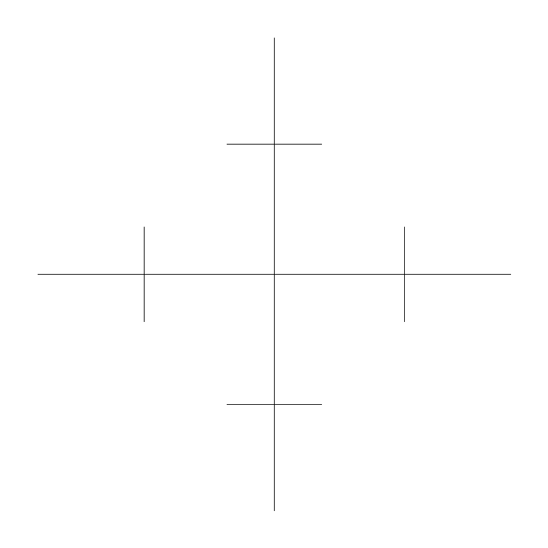
The four-way: two branch lines leaving a cross main in opposite directions, or a branch tied into two mains on a grid. Quantity is the tell here - a sheet full of crosses is a gridded system, and a grid gets calculated by iteration rather than by walking a tree back to the riser.
u, 6 to 96in, runs both centerlines out in all four directions for a symmetric 24 x 24in at default, with a port tick at 0.55u on each leg; the ticks travel with u but stay 4.8in long. All four legs plot equal, which a reducing cross is not. Hydraulically it costs what a tee costs - NFPA 13 puts them on one row - so the penalty is charged per direction change, not per fitting.
Center at origin, four ports on the axes, and no orient parameter because there is only one arrangement. That symmetry means the plan never says which leg is the supply, so annotate flow direction on a gridded main or the reviewer has to guess. Where the field substitutes two tees on a short nipple the fitting count changes and the calculation input should follow.
Sits on the cross main between run blocks, with tees taking the single-sided takeoffs and the cross reserved for paired ones. On a grid the lines leaving it reach a second cross main instead of dying in a cap.
| Plan footprint (W x H) | 24in x 24in |
|---|---|
| Units | inches |
| DXF version | R2018 |
| Insertion datum | center (0,0); 4 ports E/N/W/S |
| Parameter | Default | Range / options |
|---|---|---|
| Nominal size | 12in | 6in–96in |
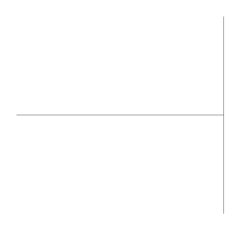
The closed end of a branch line. It carries more than its size suggests: it tells a reviewer this leg is a dead end rather than part of a loop or a grid, which decides whether the calculation is a simple tree or has to balance flow arriving from two directions.
u here runs 6 to 48in, a shorter range than the fittings, because this is only the stub past the last head - the pipe draws to 0.7u with a fixed 8in bar across the end, 8.4 x 8in at default. That bar is a symbol: cap, plug, capped nipple and grooved end cap all plot the same. Set the length to the real stub, since NFPA 13 caps the distance from the last hanger to the end sprinkler at 36in on 1in pipe, 48in on 1-1/4in and 60in on 1-1/2in and larger.
Open end at origin closing toward orient, so it snaps onto the last endpoint of a run with no trimming. Take the direction variant instead of rotating, so the block name still reads. On dry and preaction systems a capped end that is not pitched back is a trapped low point - the auxiliary drain belongs at the trap, and past 5 gal trapped it becomes a drum drip rather than a plain drain valve.
Closes the branch that started at a tee off the cross main, just past the last head. On many layouts the most remote of these carries the inspector's test connection, which then needs somewhere to discharge.
| Plan footprint (W x H) | 8.4in x 8in |
|---|---|
| Units | inches |
| DXF version | R2018 |
| Insertion datum | open (connection) end at origin (0,0); closes toward orient |
| Parameter | Default | Range / options |
|---|---|---|
| Orientation | E | N / S / E / W |
| Nominal size | 12in | 6in–48in |
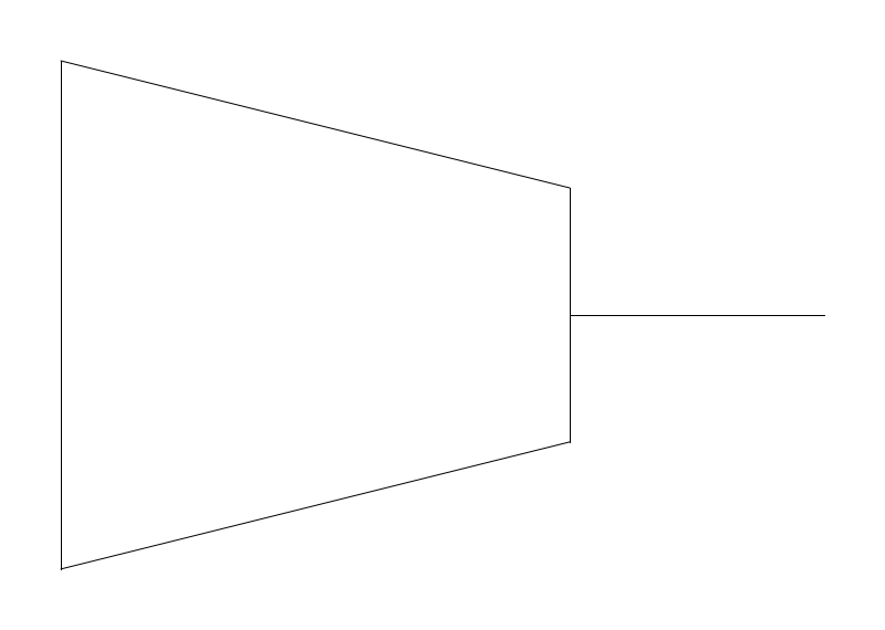
The size break on a branch line. Heads accumulate going back toward the cross main and the pipe has to grow to carry them, so a sprinkler branch is rarely one diameter end to end and the reducing coupling is where it steps.
u, 6 to 96in, sets only the drawn length. The taper itself is fixed - 8in long between an 8in face and a 4in face, then a stub out to u, 12 x 8in at default - so 2-1/2in to 2in plots the same as 4in to 1-1/4in. Note that any u below 8in leaves nothing past the taper. On a pipe-schedule job the sizes it steps between come from head count: 1in carries 2 sprinklers, 1-1/4in carries 3, 1-1/2in carries 5, 2in carries 10.
Large end at origin reducing along +X, so it goes in with the big end toward the supply; mirror rather than rotate when the line steps up the other way. The shape drawn is a concentric reducer, the normal sprinkler fitting. Eccentric reducers matter on dry-system mains, where a flat invert keeps the pipe draining, and that has to be called out or the fabricator will not know.
Lands between run blocks a head or two out from the tee at the cross main, wherever head count crosses a size break. The reducing tee is the competing detail and often the one built, collapsing this symbol and the takeoff into one fitting.
| Plan footprint (W x H) | 12in x 8in |
|---|---|
| Units | inches |
| DXF version | R2018 |
| Insertion datum | LARGE end at origin (0,0); reduces along +X (H) / +Y (V) |
| Parameter | Default | Range / options |
|---|---|---|
| Orientation | H | H / V |
| Nominal size | 12in | 6in–96in |
Branch line or cross main, drawn single-line. Head positions get inherited from the ceiling plan, but the pipe is what the hydraulic calculation actually walks: node to node from the remote area back to the riser, with every foot of this run showing up as friction loss on the way.
length runs 6 to 480in, so one insert covers a nipple between two heads or a 40ft stretch of cross main. Footprint height is 0in because a single-line pipe has no drawn width, and the block carries no diameter at all - size comes from the callout you tag it with. Length does imply support: NFPA 13 caps hanger spacing at 12ft on 1in and 1-1/4in steel and 15ft on 1-1/2in and larger, with at least one hanger per length of pipe. Listed CPVC spacing is shorter and comes from the manufacturer.
Left end at origin running +X, so runs chain by snapping to the previous endpoint and the whole fitting family lands on the same u grid. Keep pipe on its own layer, separate from heads - the head layer goes out for ceiling coordination and the pipe does not. Pitch never shows in plan; dry and preaction piping wants 1/2in per 10ft on branch lines and 1/4in per 10ft on mains, so it lives in a note.
Terminated by the cap block and interrupted by tees where branch lines leave the cross main. Every head on the sheet sits on one of these lines, and hanger and sway-brace locations get dimensioned along it.
| Plan footprint (W x H) | 12in x 0in |
|---|---|
| Units | inches |
| DXF version | R2018 |
| Insertion datum | left end (0,0); pipe/duct runs +X to (length,0) |
| Parameter | Default | Range / options |
|---|---|---|
| Length | 12in | 6in–480in |
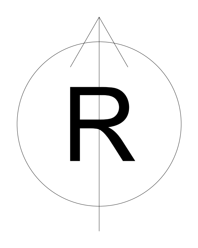
The feed riser, where the incoming main turns up out of the ground or off the lead-in and becomes the system. It is the one symbol on a sprinkler plan standing for an assembly rather than a fitting, and the space it needs is an argument with the architect, not a piping detail.
r, 3 to 8in, scales a circle with an up-arrow through it and an R tag - 8.4 x 10.92in at the 4.2in default, the height being 2.6r off the arrow rather than the circle. It is pure symbol; riser diameter comes from the calculation, not from this block. The trim does scale with the pipe: NFPA 13 sizes the main drain from riser size, reaching 2in once the riser is 4in or larger, and that drain has to discharge somewhere the architect has agreed to.
Riser center at origin sits on the pipe, so it drops onto the end of a run where the line leaves the plan vertically. Watch the R tag - it plots 0.9r high at the circle center, straight across the arrow shaft, so mask it or pull it out on a leader at small plot scale. The trim the symbol omits is the assembly: control valve, check or alarm valve, waterflow switch, main drain, gauges.
Read against the fire alarm panel that supervises its tamper and flow switches, and against the fire department connection on the exterior wall. The first run block on the sheet leaves it as the cross main.
| Plan footprint (W x H) | 8.4in x 10.92in |
|---|---|
| Units | inches |
| DXF version | R2018 |
| Insertion datum | riser center (0,0) on the pipe |
| Parameter | Default | Range / options |
|---|---|---|
| Radius | 4.2in | 3in–8in |
Standards are listed for drafting context only. A symbol drawn to a convention is not a compliance determination - verify against the governing code and the specified product. See the license and terms.
Fittings in every turn so the run reads right on the sheet. Open one in the editor or take the DXF.
Every category, every MEP orientation, DXF R2018, sorted into folders. Tell us where to send it and the download starts immediately.
If nothing happened, click here to grab the ZIP.