Pendant, upright and sidewall fire-sprinkler head CAD blocks - three physically different heads, not one symbol rotated three ways. Which one gets drawn follows the ceiling: pendant below a finished ceiling, upright on exposed pipe, sidewall where a run cannot cross the space. All three download as DXF, drawn to scale in inches.
3 blocks, 3 downloads on this page. DXF R2018, drawn in inches. Free, no signup.
DWG (R2000, converted from the DXF). PNG is the plan-view preview.
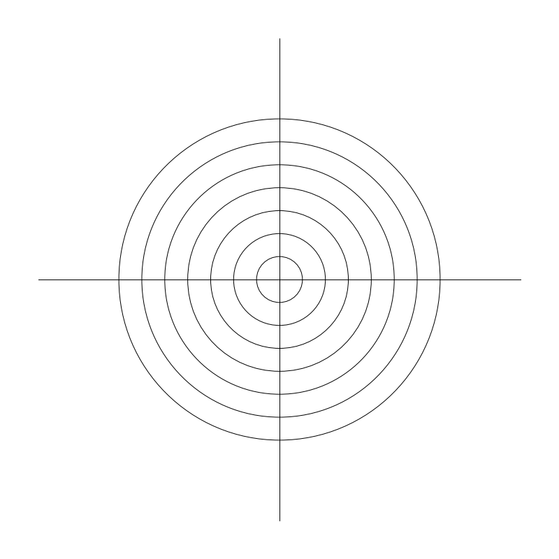
The head hanging below a finished ceiling on a drop off the branch line above. Default wherever there is a ceiling to hide pipe in - offices, corridors, retail, guest rooms - and where it lands is as much an architectural decision as a fire protection one, because it sits in the tile grid.
r, 2 to 6in, scales the symbol only, with cross arms at 1.5r for a 9 x 9in footprint at the 3in default. No real head varies that way; set r once so the sheet plots legibly. The governing numbers are protection area and spacing from NFPA 13 by hazard: up to 225 sq ft per sprinkler at 15ft spacing in light hazard under unobstructed construction, 130 sq ft at 15ft in ordinary, 100 sq ft at 12ft in extra hazard.
Filled circle with a cross here against the open circle on the upright, so check the legend before assuming. The fill is an outer circle plus six concentric rings rather than a hatch: solid at plot scale, visibly ringed if you blow the block up. Connection point is the head center, so it snaps to a tile center. A pendant on a dry or preaction system has to be a dry pendant or the drop holds water.
Coordinated on the reflected ceiling plan against lights, diffusers and dome cameras, usually the last thing placed and the first thing moved. The branch feeding its drop belongs on the piping layer, not the ceiling sheet.
| Plan footprint (W x H) | 9in x 9in |
|---|---|
| Units | inches |
| DXF version | R2018 |
| Insertion datum | pipe-connection point = head center (0,0) |
| Parameter | Default | Range / options |
|---|---|---|
| Radius | 3in | 2in–6in |
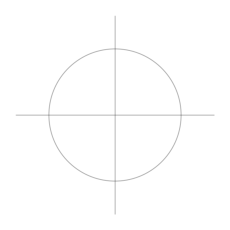
Deflector up, sitting above the branch line, for spaces with no finished ceiling: warehouse, parking garage, mechanical room, the underside of a deck. It is what you use when the pipe itself would stand in a pendant's spray pattern, and what a dry system needs so the branch drains.
r, 2 to 6in, cross arms at 1.5r, 9 x 9in at default - geometrically identical to the pendant block, so open versus filled circle is the entire distinction and symbol size says nothing about the product. Where uprights change a layout is overhead: the NFPA 13 obstruction rules want roughly three times the obstruction's dimension of clearance, capped at 24in, from anything sitting below the deflector.
Open circle with a cross, connection at head center - and that center rides on the branch line itself rather than the bottom of a drop, which is why uprights plot right on the pipe while pendants do not. Upright and pendant are separately listed and neither may be inverted, so a head drawn upright has to be scheduled upright.
Sits directly on the run blocks, so here the piping layout and the head layout are one geometry. Checked against structure, duct and high-bay lighting in the coordination model, since deflector clearance is what actually moves them.
| Plan footprint (W x H) | 9in x 9in |
|---|---|
| Units | inches |
| DXF version | R2018 |
| Insertion datum | pipe-connection point = head center (0,0) |
| Parameter | Default | Range / options |
|---|---|---|
| Radius | 3in | 2in–6in |
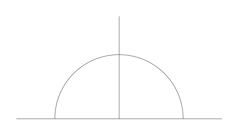
The head that throws horizontally off a wall instead of down from a ceiling. It answers the case with nowhere to hide pipe: a flat slab soffit, an existing building with no plenum, a corridor or closet where running a branch across the space is not worth the coordination.
r, 2 to 6in, draws a semicircle over a wall tick with a throw line into +Y, so unlike the round head symbols this one is asymmetric - 9.6 x 4.8in at default, about half the height of the pendant and upright blocks. That asymmetry is the information: the plan shows which way it sprays. Coverage limits are tighter than the pendant and upright allowances, and standard sidewall spray sprinklers are essentially a light hazard, smooth flat ceiling proposition.
The wall connection point is at origin on the wall line with the throw into +Y, so the block mirrors and rotates onto any wall and still reads correctly. The deflector window is the tight one: NFPA 13 puts a sidewall 4in to 6in below the ceiling against 1in to 12in for a pendant, which turns soffits, valances and deep light coves from aesthetic details into obstructions.
Drawn with the branch line running along the wall or down the corridor rather than out across the room. Checked against door swings, upper cabinets and window treatments - anything in the throw is an obstruction a ceiling layout never argues about.
| Plan footprint (W x H) | 9.6in x 4.8in |
|---|---|
| Units | inches |
| DXF version | R2018 |
| Insertion datum | wall-connection point on wall line (0,0); throws +Y |
| Parameter | Default | Range / options |
|---|---|---|
| Radius | 3in | 2in–6in |
Standards are listed for drafting context only. A symbol drawn to a convention is not a compliance determination - verify against the governing code and the specified product. See the license and terms.
Device symbols for the fire protection sheet. Open one in the editor or take the DXF.
Every category, every MEP orientation, DXF R2018, sorted into folders. Tell us where to send it and the download starts immediately.
If nothing happened, click here to grab the ZIP.