Twenty-one plumbing pipe CAD blocks built from seven fittings - 45 and 90-degree elbows, tee, cross, cap, reducer and straight run - drawn in the orientations a run actually needs. Single-line schematic at the scale a plumbing plan is drafted, sized on nominal pipe. Each one is a free DXF download.
7 blocks, 21 downloads on this page. DXF R2018, drawn in inches. Free, no signup.
DWG (R2000, converted from the DXF). PNG is the plan-view preview.
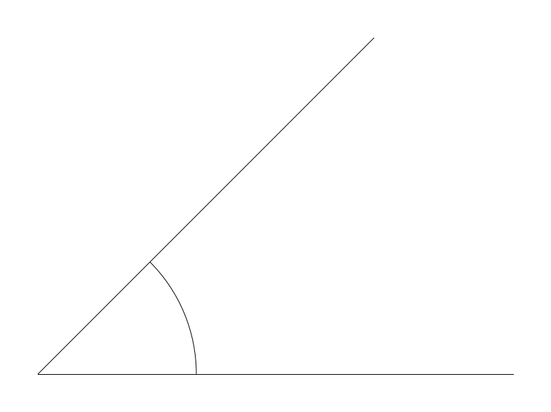
The one-eighth bend, and the change of direction drainage prefers. Two of them build an offset around a beam or a column without the abrupt turn that drops solids out of suspension. On water supply it is simply the cheaper turn in head loss, worth taking anywhere the run has room to swing wide.
The angled leg projects u/sqrt(2) on both axes while the straight leg runs the full u, giving a 12 x 8.5in footprint at the default and holding that 1 to 0.707 proportion anywhere in the 6-96in range. Read it as drawing geometry only. Center-to-face on a real 1/8 bend is far shorter than the drawn leg, socket make-up consumes more of it again, and no cut length should ever be scaled off this block.
The datum is the bend vertex, the theoretical intersection of the two centerlines rather than a fitting face, so trimming both runs into it keeps the geometry clean at any u. Where two of these stack close together on a drain, the turn is being aggregated even though each fitting is only 45 degrees, and it is the total that access rules look at.
Drawn in pairs to form an offset, and downstream of a combination wye where a branch swings into the direction of flow. Where the pair sits tight against structure, a cleanout normally belongs at the upper bend.
| Plan footprint (W x H) | 12in x 8.49in |
|---|---|
| Units | inches |
| DXF version | R2018 |
| Insertion datum | bend vertex (0,0); axis leg + 45deg leg into orient quadrant |
| Parameter | Default | Range / options |
|---|---|---|
| Orientation | NE | NE / NW / SE / SW |
| Nominal size | 12in | 6in–96in |
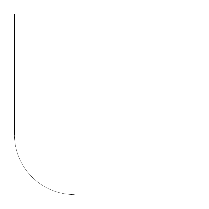
Drawn in the plane of the sheet this is a horizontal-to-horizontal turn, the case drainage restricts. The IPC change-of-direction table allows a plain quarter bend there only on fixture drains 2in and smaller; larger turns take a long sweep, two 1/8 bends, or a combination wye and 1/8 bend. On supply it is just the costliest turn for head loss.
u sets leg length across a 6in to 96in range and both ports sit u out from the bend vertex, so the block always plots square, 12 x 12in by default. The drawn corner radius is graphic. It does not separate a short-turn quarter bend from a long-sweep pattern, and those are different fittings with different laying lengths and very different standing in the drainage code, so the pattern has to be carried by the tag or the fitting schedule.
This symbol cannot show a turn out of the page. An elbow rising or dropping appears in plan as an ell-up or ell-down marker, not as this block, and mixing the two is the fastest way to lose an elevation change on a plan sheet. Reserve it for turns that stay horizontal, and annotate the ones that do not.
Takes a straight run at each end and, on drainage, usually gets a cleanout at or near the turn. On copper supply it is one of the fittings tallied when equivalent length is checked against the pressure available at the most remote fixture.
| Plan footprint (W x H) | 12in x 12in |
|---|---|
| Units | inches |
| DXF version | R2018 |
| Insertion datum | bend vertex (0,0); two ports at u along the two orient dirs |
| Parameter | Default | Range / options |
|---|---|---|
| Orientation | NE | NE / NW / SE / SW |
| Nominal size | 12in | 6in–96in |
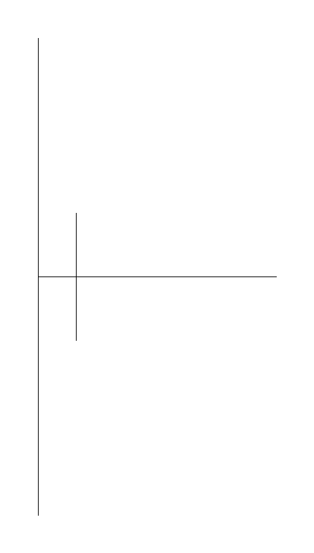
A branch connection. With the branch drawn in the plane of the page this is a horizontal-to-horizontal junction, which on a drain is wye territory: a sanitary tee laid on its back discharges the branch square into the far wall of the run and is not a drainage fitting in that position. On water supply the same geometry is unremarkable.
Run legs reach u each way from center and the branch stub u out from it, so the east variant plots 12 wide by 24 tall at the 12in default and holds u by 2u across the 6-96in range. A reducing tee is written run x run x branch, which means 4x4x2 and 4x2x4 are different fittings that draw the same way here. The tag has to carry that order, because the symbol has no way to.
The datum is the center of the run rather than the branch outlet, so cycling branch through N/S/E/W swings the stub while the main line stays unbroken and its centerline stays put. On DWV, a tee turned so the branch rises is a vent takeoff and one turned down is a fixture drop; annotate which, because in plan the two are the same picture.
Feeds a fixture branch or a riser off a main and, on drainage, is followed within a short developed length by the trap and vent it serves. Downstream of it the fixture unit count on the main steps up, which is where the next pipe size gets checked.
| Plan footprint (W x H) | 12in x 24in |
|---|---|
| Units | inches |
| DXF version | R2018 |
| Insertion datum | run center (0,0); run perpendicular to branch, branch stub +orient |
| Parameter | Default | Range / options |
|---|---|---|
| Branch | E | N / S / E / W |
| Nominal size | 12in | 6in–96in |
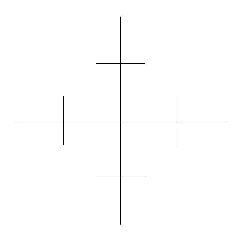
A four-way junction on pressurized pipe: a water main splitting at a corridor intersection, a plant loop fed both directions off a header. Sanitary drainage does not use a straight cross. Its equivalent is a double fixture fitting, and even that is restricted where back-to-back water closets discharge into it unless the barrel is upsized.
Every port lands exactly u from the center, so the symbol always plots 2u square, 24 x 24in at the 12in default, with u free anywhere between 6in and 96in. None of that describes the fitting. A reducing cross is called out run-run-branch-branch, 6x6x4x4 for instance, and both branch sizes have to come off the pipe tags. Set u once per sheet so junctions read consistently against the tees around them.
No orient parameter exists, because the fitting is symmetric about both axes and the only rotation worth applying is 45 degrees where two mains cross on a diagonal. Center insertion puts the datum on the intersection of the two centerlines, which is the point a site plan dimensions to and the point thrust restraint is measured from on buried main.
Reads with gate or butterfly valves on three or four legs, because a cross usually exists to sectionalize a loop that has to be isolated a quadrant at a time. Buried, it is drawn with valve boxes and thrust blocking.
| Plan footprint (W x H) | 24in x 24in |
|---|---|
| Units | inches |
| DXF version | R2018 |
| Insertion datum | center (0,0); 4 ports E/N/W/S |
| Parameter | Default | Range / options |
|---|---|---|
| Nominal size | 12in | 6in–96in |
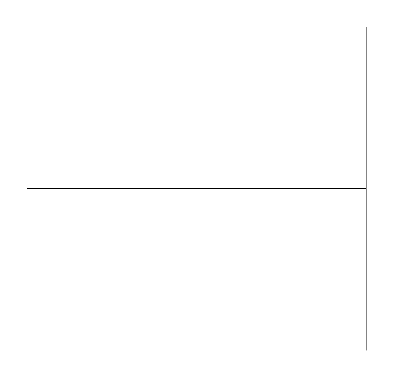
Closes a line end. A stub-out held for a future fixture group, a capped branch at a tenant demise wall, or the temporary closure a DWV rough-in test is pressured against. On drainage it also ends a horizontal run, where the code usually wants a cleanout plug at that point rather than a plain cap.
Unlike the rest of the plumbing routing family, u stops at 48in here instead of 96in, and it governs symbol weight rather than pipe size. At the 12in default the closure body plots 8.4 x 8in, short of a full unit because only the cap is drawn, not a length of pipe behind it. Match u to the fittings upstream so the terminated end reads at the same scale, and let the pipe tag state the actual diameter.
Origin sits on the open connection end and the body builds outward past it, so snapping to the last endpoint of a run adds length beyond that point. That is correct for a cap, which slips over the pipe end, and wrong for a plug, which seats inside a fitting hub. Note in the callout which one the spec calls for.
Sits at the far end of a straight run, or on the unused port of a tee left for future work. On potable supply it marks the dead leg a plan reviewer will question, so draw it with the isolation valve that lets the branch be cut in later.
| Plan footprint (W x H) | 8.4in x 8in |
|---|---|
| Units | inches |
| DXF version | R2018 |
| Insertion datum | open (connection) end at origin (0,0); closes toward orient |
| Parameter | Default | Range / options |
|---|---|---|
| Orientation | E | N / S / E / W |
| Nominal size | 12in | 6in–48in |
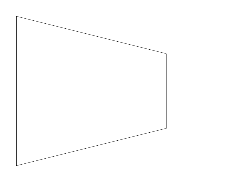
A size step in the line. On water distribution it marks where a main hands off to a branch and where velocity is pulled back into range as demand drops off the end of a run. On sanitary drainage the same body is read the other way round, as an increaser, because a drain is not permitted to get smaller in the direction of flow.
The body plots u long by 0.73u across the large face, 12 x 8.8in at the default, and holds that proportion anywhere in the 6in to 96in range. A 4x3 increaser and a 12x8 water reduction therefore draw identically, so both diameters have to appear in the pipe tags either side of it. Say on the sheet when a reducing bushing is intended instead of a coupling: a bushing seats inside the hub and leaves an internal ledge, which is why DWV work avoids them.
The large end sits at origin and the body narrows along +X, so on a drainage plan with flow running +X the block as inserted contradicts the code. Mirror it and let the pipe grow in the direction of flow. On horizontal water lines add concentric or eccentric to the callout; the symbol shows neither, and on a pump suction the flat side goes up so no air pocket can form.
Falls just past a tee where a branch leaves a main, ahead of a meter or backflow assembly sized below the service feeding it, and on drainage immediately downstream of the point where accumulated fixture units push the pipe up a size.
| Plan footprint (W x H) | 12in x 8.8in |
|---|---|
| Units | inches |
| DXF version | R2018 |
| Insertion datum | LARGE end at origin (0,0); reduces along +X (H) / +Y (V) |
| Parameter | Default | Range / options |
|---|---|---|
| Orientation | H | H / V |
| Nominal size | 12in | 6in–96in |
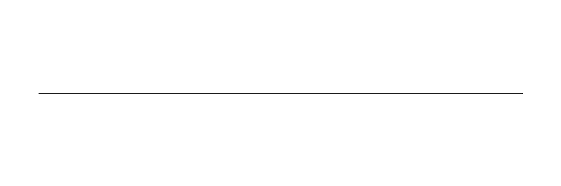
The segment between fittings, and the only block in this family that carries slope, support and cover. Drawn flat in plan it hides its own fall: at 1/8in per foot the 40-foot maximum length here drops 5in end to end, which is exactly the dimension that collides with a joist bottom or a ceiling grid.
length accepts 6in through 480in, so one block covers a 6in nipple or a 40-foot main, and it plots with zero height, a single line with no drawn wall. Diameter lives in the tag, not the geometry, and that matters because slope follows size: the same 40-foot run falls 10in at 1/4in per foot and only 2-1/2in at 1/16in per foot. Which rate applies is decided by the size in the tag, not the length typed in here.
Insertion at the left end running +X lets segments chain end to end without accumulating gaps, which matters when quantities get read off the drawing. On drainage, note invert at both ends rather than trusting the plan line, and mark direction of flow; the block is symmetric and will not tell a reviewer which way it drains.
Terminated by an elbow, tee or cap at each end and hung at whatever interval the material demands. On a long horizontal drain it is where cleanout spacing gets checked, since the run is what accumulates developed length between access points.
| Plan footprint (W x H) | 12in x 0in |
|---|---|
| Units | inches |
| DXF version | R2018 |
| Insertion datum | left end (0,0); pipe/duct runs +X to (length,0) |
| Parameter | Default | Range / options |
|---|---|---|
| Length | 12in | 6in–480in |
Standards are listed for drafting context only. A symbol drawn to a convention is not a compliance determination - verify against the governing code and the specified product. See the license and terms.
Fittings and piping symbols for the plumbing plan and riser. Open one in the editor or take the DXF.
Every category, every MEP orientation, DXF R2018, sorted into folders. Tell us where to send it and the download starts immediately.
If nothing happened, click here to grab the ZIP.