Ball, check and gate valve CAD blocks in P&ID convention, all three on the same 24x12in body so a valve swap on the diagram does not move the line. The distinction is in the symbol interior, which is the whole point of a P&ID valve: the reader identifies the type at a glance without a callout. Free DXF downloads.
3 blocks, 3 downloads on this page. DXF R2018, drawn in inches. Free, no signup.
DWG (R2000, converted from the DXF). PNG is the plan-view preview.
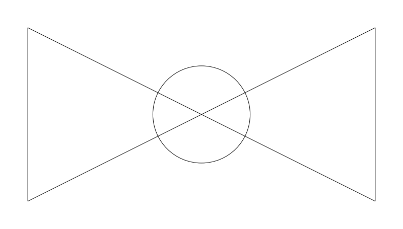
The quarter-turn isolation valve, and the symbol that appears more than any other on a process sheet. It goes wherever a line needs a fast, full-bore open or shut: pump suction and discharge, equipment isolation, drains and sample points.
The bowtie body runs 2u long by u tall, 24 x 12in at the default, with the ball drawn at 0.28u inside it and the bore shown open on the pipe axis. Valve size, pressure class and body material never come from u; they come from the line spec and the valve schedule.
The block carries a single-sided quarter-turn lever off the stem, which is the correct operator glyph for a ball or plug valve and also means the symbol is not symmetric top to bottom or left to right. Fix the lever direction once and hold it sheet-wide. When an actuator replaces the lever, diaphragm, motor or solenoid, it stacks on the same stem and the stack direction has to stay consistent too.
The most common grouping is one each side of the pump, plus a small-bore ball at every drain, vent and sample point on the sheet. The small ones are what a first pass leaves off.
| Plan footprint (W x H) | 24in x 12in |
|---|---|
| Units | inches |
| DXF version | R2018 |
| Insertion datum | center, pipe axis X |
| Parameter | Default | Range / options |
|---|---|---|
| Nominal size | 12in | 6in–24in |
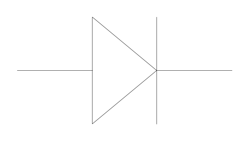
The one inline symbol on a P&ID that has a direction. It marks a valve that passes flow one way and closes on reversal: pump discharges, tie-ins to a shared header, anywhere reverse flow would drain a vessel back through the equipment.
Held at 2u long by u tall like the rest of the inline family, so a string of valves along one line reads at a single height. Body style never comes from u either, and the difference matters: a wafer check is far shorter face-to-face than a flanged swing check, which the schematic length does not reflect at all.
Built with flow toward +X, and drawn specifically as a swing check, with the disc leaf hanging off a hinge pin at the top of the seat bar on the inlet side of the seat and an arrowhead on the outlet stub. That makes it the wrong symbol for a lift or dual-plate check unless your legend says otherwise. Rotate it to follow the line and never mirror it; a backwards check is a routine review comment.
Immediately downstream of the pump and upstream of the discharge isolation valve, so the pump can be opened for work while the check holds the header back.
| Plan footprint (W x H) | 24in x 12in |
|---|---|
| Units | inches |
| DXF version | R2018 |
| Insertion datum | center, pipe axis X (flow +X) |
| Parameter | Default | Range / options |
|---|---|---|
| Nominal size | 12in | 6in–24in |

The bowtie with a rising stem and handwheel: the manual gate valve, and the shape every other valve symbol on the sheet is a variation of. Specified for on/off isolation on larger lines, where full-bore opening and cost per inch both weigh in.
2u long by u tall, 24 x 12in at the default, so a run of isolation valves plots at the same height as the ball and check symbols. What u will not tell you is why gate was chosen over ball on a large line, which comes down to cost and weight rather than anything visible in the geometry.
The stem, bonnet yoke and edge-on handwheel are drawn inside the body envelope on the +Y side, so the symbol is symmetric left to right but not top to bottom, and mirroring across a horizontal axis puts the handwheel under the pipe. Because this is the base geometry for the legend, hold its line weight and proportion fixed; any variant built from it by adding fill or a different operator has to stay distinguishable at a half-size plot.
The habitual grouping is a gate valve with a blind flange and a drain at the end of a header, plus one on each side of anything isolated for maintenance.
| Plan footprint (W x H) | 24in x 12in |
|---|---|
| Units | inches |
| DXF version | R2018 |
| Insertion datum | center, pipe axis X |
| Parameter | Default | Range / options |
|---|---|---|
| Nominal size | 12in | 6in–24in |
Standards are listed for drafting context only. A symbol drawn to a convention is not a compliance determination - verify against the governing code and the specified product. See the license and terms.
Process symbols for the diagram you are building. Open one in the editor or take the DXF.
Every category, every MEP orientation, DXF R2018, sorted into folders. Tell us where to send it and the download starts immediately.
If nothing happened, click here to grab the ZIP.