Five P&ID equipment and symbol CAD blocks: centrifugal pump, tank or vessel, flange, reducer and instrument bubble. Together they cover what sits between the valves on a process diagram - the thing that moves the fluid, the thing that holds it, the connections, and the instrument that watches it. All drawn to P&ID convention and downloadable as DXF.
5 blocks, 5 downloads on this page. DXF R2018, drawn in inches. Free, no signup.
DWG (R2000, converted from the DXF). PNG is the plan-view preview.
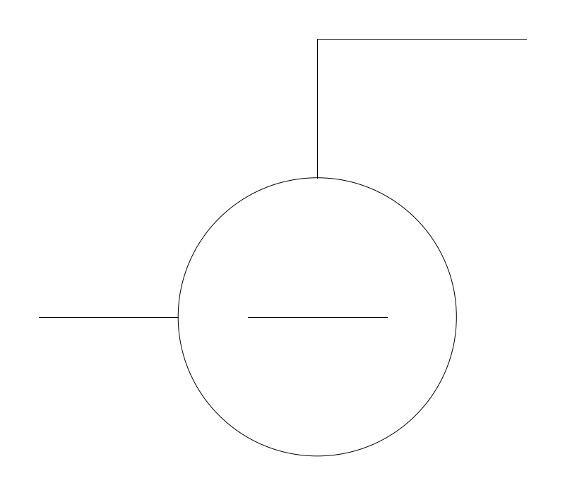
The casing circle with an impeller and a tangential discharge riser, standing for a rotodynamic pump. It anchors a whole section of sheet: suction line, discharge line, isolation each side, a check on the discharge and usually a gauge, all of which orient off this one symbol.
u is symbol scale, not equipment scale. The casing is 1.2u across, and the suction stub and discharge riser push the extents to 25.2 x 21.6in. The same block stands in for a 3in end-suction unit and a large between-bearings machine. Footprint, baseplate and nozzle sizes come off the vendor drawing and belong on the equipment layout, not here.
Drawn suction in from -X and discharge up then over toward +X, with flow arrowheads on both. Rotate in ninety-degree steps to match how the line runs and let the piping meet the symbol rather than the reverse. Do not mirror it: mirroring reverses the drawn impeller vane sweep and puts the vanes at odds with the arrows. Equipment tag goes beside the symbol, not inside it.
Rarely drawn alone. From the suction side out, the conventional string is isolation valve, reducer, pump, check valve, isolation valve, and a reviewer looks for that sequence before reading anything else on the line.
| Plan footprint (W x H) | 21.6in x 21.6in |
|---|---|
| Units | inches |
| DXF version | R2018 |
| Insertion datum | casing center (nozzles extend beyond) |
| Parameter | Default | Range / options |
|---|---|---|
| Nominal size | 12in | 6in–24in |
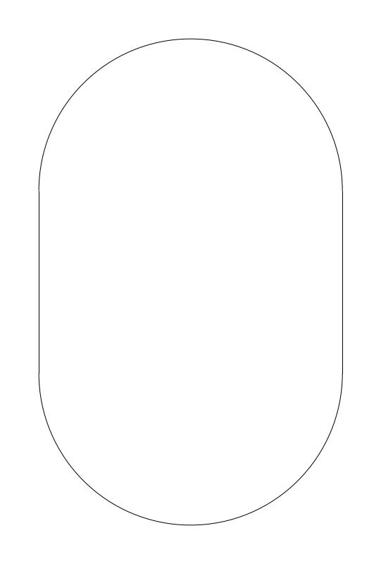
The upright rounded-end outline standing in for a tank, drum, column or receiver. It works as a hub on the sheet: level instrumentation, a vent or relief path, an inlet, an outlet and usually a drain all terminate on it.
The 12 x 19.2in default is a fixed 1-to-1.6 symbol proportion, not a vessel proportion; a 55-gallon drum and a thirty-foot column get the same block. Equipment symbols are drawn larger than inline symbols only so nozzles have somewhere to land and the tag has room to sit.
Center insertion sits at the centroid. The block already carries top and bottom centerline nozzle necks and the head-to-shell weld seams, so what you add are side nozzles drawn to the shell where the service needs them. It also ships with a dashed operating level across the shell, the standard cue that the vessel holds inventory; erase it where the vessel is not meant to show one. Nozzle position on a P&ID is schematic, top, side or bottom, and commits to no dimension.
The instrument bubble is its constant companion, since level is the measurement a vessel almost always needs. The next thing a reviewer looks for is a valved drain at the bottom outlet.
| Plan footprint (W x H) | 12in x 19.2in |
|---|---|
| Units | inches |
| DXF version | R2018 |
| Insertion datum | vessel center |
| Parameter | Default | Range / options |
|---|---|---|
| Nominal size | 12in | 6in–24in |
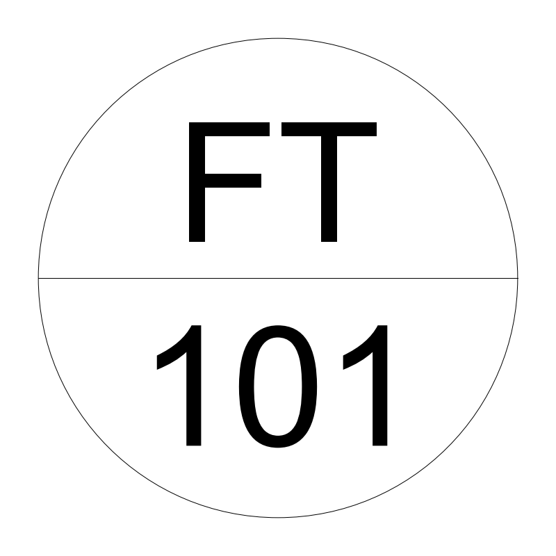
The tagged circle that turns a length of pipe into an instrumented loop. Every transmitter, indicator, controller and switch lives inside one, and the tag is what links the drawing to the instrument index and the loop sheet.
u sets bubble diameter at 1.2u, 14.4in at the default, and nothing physical: the balloon is the same size whether it tags a thermowell or a Coriolis meter. If the letters will not sit legibly in the upper half at plot scale, raise u rather than shrinking the text.
The tag splits at the hyphen, letters above the divider and loop number below. First letter is the measured variable and the succeeding letters the function, so FT-101 reads flow transmitter, loop 101. Note that under ISA-5.1 a horizontal bar across a balloon also carries mounting information, a plain circle meaning field-mounted and a solid line meaning an accessible primary location, so settle which reading your legend assigns to the divider this block draws before the sheet is issued.
Attaches to whatever it measures by a signal line off the bubble edge: discharge pressure or flow at the pump, level on the vessel. The line type running between bubble and process does as much work as the tag inside it.
| Plan footprint (W x H) | 14.4in x 14.4in |
|---|---|
| Units | inches |
| DXF version | R2018 |
| Insertion datum | bubble center |
| Parameter | Default | Range / options |
|---|---|---|
| Tag | FT-101 | FT-101 |
| Nominal size | 12in | 6in–24in |
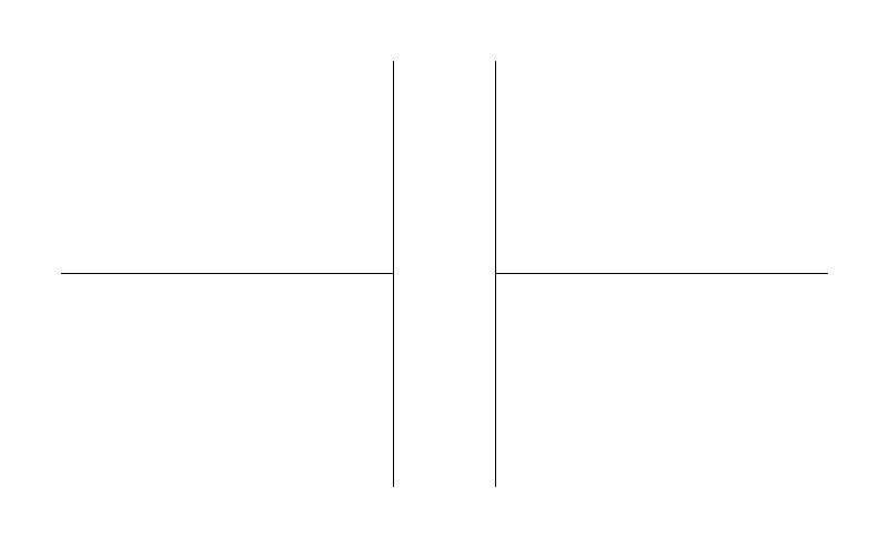
The pair of bars across a process line marking a bolted joint. Nobody draws every flange on a P&ID; one appears where the joint carries information, a spec break between pipe classes, a blind for a future tie-in, or the break that lets a spool come out.
u is schematic only. The faces stand a half-u off the pipe axis and the stubs run 0.9u each way, giving 21.6 x 12in at the default. A joint at u=12 says nothing about whether it is 2in Class 150 or 12in Class 300, so set u once per sheet to keep every inline symbol matched and let the line number carry size and rating.
The block draws its own pipe stubs, tapered hubs and a gasket line, so it drops onto a run at a nearest snap and overlays the pipe instead of needing a trim. Joint-center insertion on a horizontal axis. Hold it at pipe line weight; at equipment weight the two bars start reading as a piece of hardware.
Turns up in pairs around whatever has to be removable: the pump, a control valve station, a meter run. If a reviewer can trace two of these bracketing an item, that item comes out without cutting pipe.
| Plan footprint (W x H) | 21.6in x 12in |
|---|---|
| Units | inches |
| DXF version | R2018 |
| Insertion datum | joint center, pipe axis X |
| Parameter | Default | Range / options |
|---|---|---|
| Nominal size | 12in | 6in–24in |
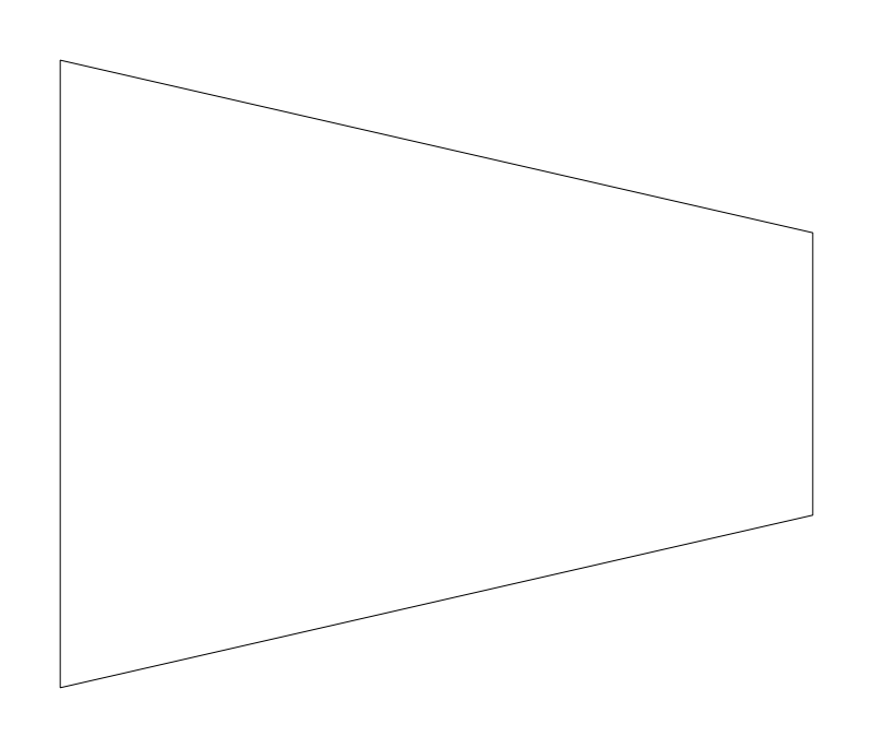
The trapezoid marking a diameter change. It shows up wherever a line steps size, at pump nozzles that do not match the line, at control valve stations, at equipment connections. Small on the sheet but load-bearing, because the line number changes across it.
u scales the symbol, not the reduction. The body runs 1.2u long and steps from a full u face down to 0.45u, a fixed proportion. A reducer at u=12 could be 6x4 or 24x18; the actual sizes live in the line numbers either side of it.
This block is the concentric reducer, and the drawn centerline through the body is what says concentric. An eccentric reducer has one face flush and is a separate legend symbol, not a rotation of this one. The large end is built toward -X, so when the line steps up you mirror rather than rotate, and wherever an eccentric is used the P&ID should call its orientation explicitly instead of leaving the decision to the piping designer.
Two of them bracket a control valve station, where the line steps down into a valve smaller than the run and back up after it. The other habitual location is hard against a pump, since pump nozzles rarely match the lines serving them.
| Plan footprint (W x H) | 14.4in x 12in |
|---|---|
| Units | inches |
| DXF version | R2018 |
| Insertion datum | center, pipe axis X (large end -X) |
| Parameter | Default | Range / options |
|---|---|---|
| Nominal size | 12in | 6in–24in |
Standards are listed for drafting context only. A symbol drawn to a convention is not a compliance determination - verify against the governing code and the specified product. See the license and terms.
Equipment and instruments for the process diagram. Open one in the editor or take the DXF.
Every category, every MEP orientation, DXF R2018, sorted into folders. Tell us where to send it and the download starts immediately.
If nothing happened, click here to grab the ZIP.