Twelve security CAD blocks covering both halves of a security drawing: the field devices - dome and bullet cameras, an access-control keypad, a PIR motion detector with its coverage wedge, a door position switch, a panic button and a CO2 monitor - the head end they report to, an alarm control panel, an NVR rack and a server rack, and the two things a secured room is built round, a 30in floor safe and a queue stanchion drawn with the belt to the next post. The cameras and the detector carry aim and field-of-view parameters, so a coverage plan can be drawn rather than sketched. Free DXF downloads.
12 blocks, 12 downloads on this page. DXF R2018, drawn in inches. Free, no signup.
DWG (R2000, converted from the DXF). PNG is the plan-view preview.

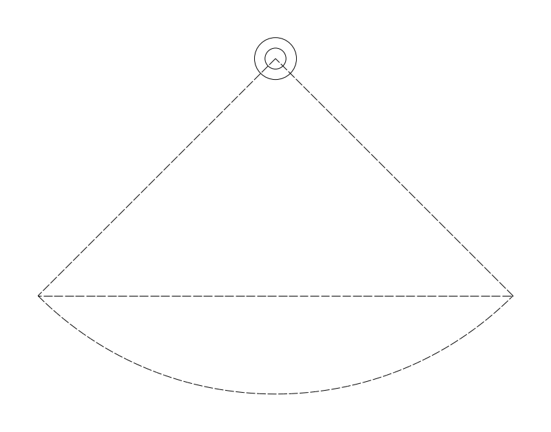
Ceiling-mounted camera under a tinted dome. It is the interior standard for retail floors, lobbies, corridors and cash-handling positions, where hiding the aim direction and resisting a casual grab matter more than reach.
The 4 to 9 in dome diameter runs from a compact indoor housing to a vandal-resistant or multi-sensor unit, and at plot scale it is nearly invisible next to the coverage wedge. Field of view goes to 360 degrees here, which the bullet's 120 degree ceiling does not reach; that top end is a fisheye or multi-imager covering a whole room from one point. The 67.9 x 51 in default is the 90 degree wedge at 48 in of reach, plus the dome body.
The insertion point is the mount center at the ceiling, so the block lands on a grid intersection or a tile center and the wedge rotates about that same point. Split it across two layers: the dome on the reflected ceiling plan, the coverage wedge on a security layer that gets turned off for the ceiling sheet.
Coordinated against the ceiling grid, air diffusers, sprinkler heads and lay-in fixtures. A dome landing on a tile joint or tucked under a light fixture is the most common ceiling clash on a security sheet.
| Plan footprint (W x H) | 67.88in x 51in |
|---|---|
| Units | inches |
| DXF version | R2018 |
| Insertion datum | mount center (ceiling) |
| Parameter | Default | Range / options |
|---|---|---|
| Diameter | 6in | 4in–9in |
| Field of view | 90° | 30°–360° |
| Reach | 48in | 12in–240in |
| Aim bearing | 270° | 0°–360° |
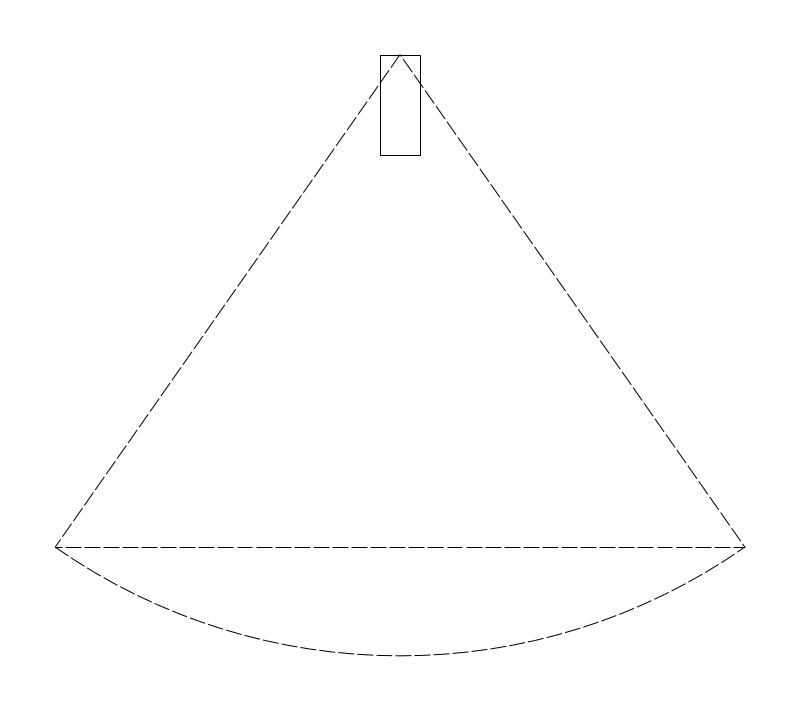
Directional fixed camera on an arm or bracket. It is the usual choice outdoors, on warehouse walls and along fence lines, where a visible housing doing visible work is part of the intent. The security designer draws it together with its coverage cone, because a camera symbol without a cone tells a reviewer nothing.
The 6 to 12 in length is body plus bracket, but it is not what sets the footprint. Plotted extents come from field of view, 20 to 120 degrees, and drawn reach, 12 to 240 in. The default 70 degree cone at 48 in gives the 55.1 x 48 in footprint; widen the field of view and the block gets wider without the camera moving.
The insertion point is the mount at the camera body, so the block rotates about the device and the cone sweeps with it. Aim defaults to 270 degrees, which is almost never right once the camera is placed, so reset it before you commit. Screen the cone onto its own layer so a dozen of them do not turn the floor plan into a solid field.
Laid out against the dome cameras: bullets take the perimeter, loading docks and long approaches while domes take interior ceilings. Both home back to the NVR rack, and cable run length is the practical limit on where a bullet can go.
| Plan footprint (W x H) | 55.06in x 48in |
|---|---|
| Units | inches |
| DXF version | R2018 |
| Insertion datum | mount point |
| Parameter | Default | Range / options |
|---|---|---|
| Length | 8in | 6in–12in |
| Field of view | 70° | 20°–120° |
| Reach | 48in | 12in–240in |
| Aim bearing | 270° | 0°–360° |
Wall-mounted entry device at a controlled door: PIN pad, credential reader, or both in one housing. It cross-references the door hardware schedule, because the door, the lock, the power transfer hinge and the reader are one assembly and get bought as one.
4 x 6 in reads as a single-gang reader. The 3 to 6 in width covers a narrow mullion-mount unit up to a keypad with a display. The 6 in default depth is larger than the width, which is a legibility allowance at plot scale rather than a real projection: an actual reader stands off the wall about an inch.
Placing from the wall line is what puts the device on the correct face of the opening: reader outside the secured area, request-to-exit device inside, both clear of the latch-side approach a person needs to work the door. Mirror the block rather than rotating it when a door hand flips, or the reader ends up inside the space it is supposed to protect.
Drawn with the door it controls and with the alarm panel or access controller supervising it. The home-run distance back to that panel is usually what decides whether an opening is practical to control at all.
| Plan footprint (W x H) | 4in x 6in |
|---|---|
| Units | inches |
| DXF version | R2018 |
| Insertion datum | wall-mount point on wall line |
| Parameter | Default | Range / options |
|---|---|---|
| Width | 4in | 3in–6in |
| Depth | 6in | 4in–8in |
Wall-mounted enclosure holding an intrusion alarm control: board, transformer, standby battery and dialer or network communicator. It goes in back-of-house space, an IT closet or an electrical room, never on public frontage, and it is a device the security integrator owns while the electrical engineer only feeds it.
12 x 4 in fits a common sheet-metal can. Take the width toward 16 in for an enclosure carrying zone expanders or a larger standby battery. The depth range matters more than the width: at 3 in the can stays inside the 4 in protrusion limit that applies to a corridor wall, and at 6 in it does not.
The datum on the wall line puts the can off the wall face at its true projection. Keep it on the security layer rather than power, but flag that it still needs a dedicated circuit from the electrical engineer, which is the coordination item that gets missed. If what is being drawn is actually a fire alarm control unit, it belongs to a different system, a different layer and a different code path, even though the two look identical in plan.
Drawn with the keypads it supervises and the door contacts homed back to it, usually on the same wall as the NVR rack so one conduit path serves both.
| Plan footprint (W x H) | 12in x 4in |
|---|---|
| Units | inches |
| DXF version | R2018 |
| Insertion datum | wall-mount point on wall line |
| Parameter | Default | Range / options |
|---|---|---|
| Width | 12in | 8in–16in |
| Depth | 4in | 3in–6in |
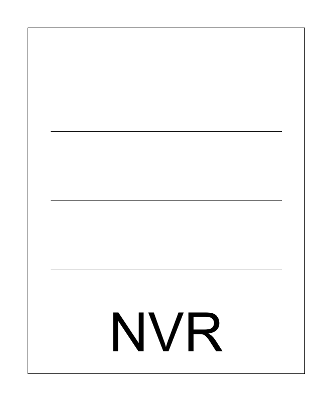
Cabinet holding the network video recorder, its drive array, the PoE switch feeding the cameras and a UPS. It sits in an IT closet or a security office. The electrical engineer feeds it and the mechanical engineer has to carry away the heat it makes, and neither number is knowable until someone counts the cameras.
24 x 30 in is a compact floor-standing cabinet. The 20 to 30 in width brackets a 19 in equipment panel plus frame and side room for cable management. The 24 to 40 in depth is where recorders diverge from switches: a switch cabinet stays shallow, a drive-loaded recorder chassis needs the deep end.
Origin at the near-left corner lets the cabinet reference a wall face or a room corner directly. Add a dashed service zone front and rear, sized to the swing of the cabinet's own door; a bare footprint makes a security closet look like it has room it does not have.
Every camera on the sheet terminates here, so the dome and bullet blocks all home to this cabinet. Coordinate it against the electrical panel and the closet door swing before the camera count grows.
| Plan footprint (W x H) | 24in x 30in |
|---|---|
| Units | inches |
| DXF version | R2018 |
| Insertion datum | back-left corner on wall line (service face at +Y) |
| Parameter | Default | Range / options |
|---|---|---|
| Width | 24in | 20in–30in |
| Depth | 30in | 24in–40in |
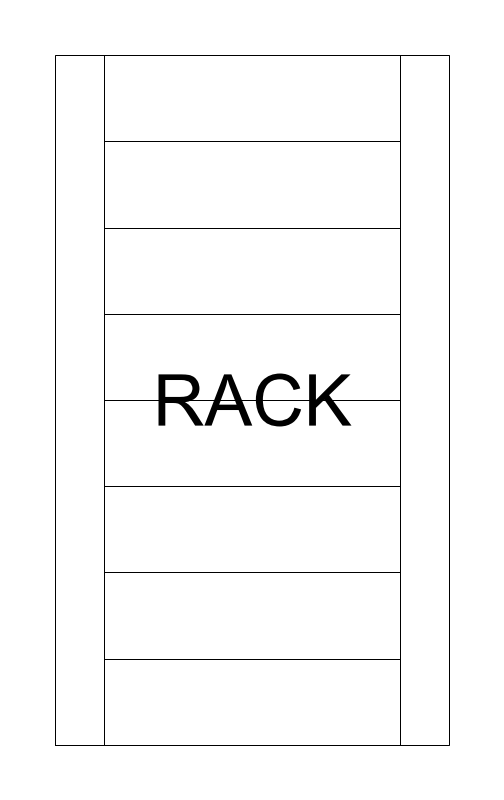
Full-height cabinet in an MDF, IDF or IT room carrying switches, servers, patch panels and PDUs. It shows up three times: architectural for floor space, electrical for its feed and receptacle type, mechanical for its heat load. The heat load is the one that changes the room.
24 x 42 in is the common cabinet, roughly 600 mm by 1070 mm. The 36 to 48 in depth is what separates a patch cabinet from a server cabinet, and it is the dimension that eats an IT room. At the 23 in low end the block stops representing an enclosure and starts representing a frame, whether a 19 in panel with its rails or a 23 in telecom relay rack.
Corner insertion is what makes a row workable: array it along a wall or back to back for a hot aisle without recomputing a center each time. Draw front clearance and rear clearance as two separate rectangles. The rear one is the one that gets forgotten and then blocked by a door swing or a wall-mounted panel.
Arrayed against itself, since IT rooms get rows rather than single cabinets, and coordinated with the overhead cable tray or ladder rack, which has to land over the cabinet tops rather than over the aisle.
| Plan footprint (W x H) | 24in x 42in |
|---|---|
| Units | inches |
| DXF version | R2018 |
| Insertion datum | back-left corner on wall line (service face at +Y) |
| Parameter | Default | Range / options |
|---|---|---|
| Width | 24in | 23in–30in |
| Depth | 42in | 36in–48in |

| Plan footprint (W x H) | 42.43in x 33in |
|---|---|
| Units | inches |
| DXF version | R2018 |
| Insertion datum | device at wall line (coverage field dashed into the room) |
| Parameter | Default | Range / options |
|---|---|---|
| Width | 4in | 3in–6in |
| Depth | 3in | 2in–4in |
| Reach | 30in | 18in–60in |
| Field of view | 90° | 60°–110° |
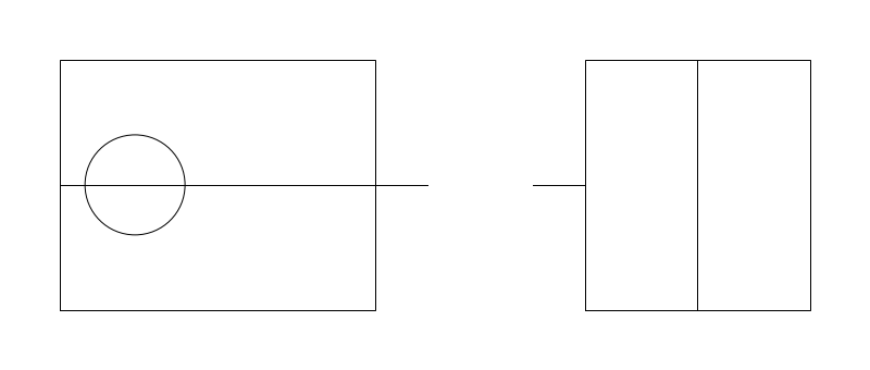
| Plan footprint (W x H) | 3in x 1in |
|---|---|
| Units | inches |
| DXF version | R2018 |
| Insertion datum | switch on the frame line (magnet on the leaf, gap between) |
| Parameter | Default | Range / options |
|---|---|---|
| Width | 3in | 2in–5in |
| Depth | 1in | 0.75in–2in |
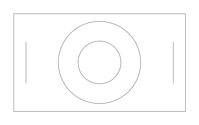
| Plan footprint (W x H) | 3.5in x 2in |
|---|---|
| Units | inches |
| DXF version | R2018 |
| Insertion datum | back-center on wall line |
| Parameter | Default | Range / options |
|---|---|---|
| Width | 3.5in | 2.5in–6in |
| Depth | 2in | 1.5in–3in |
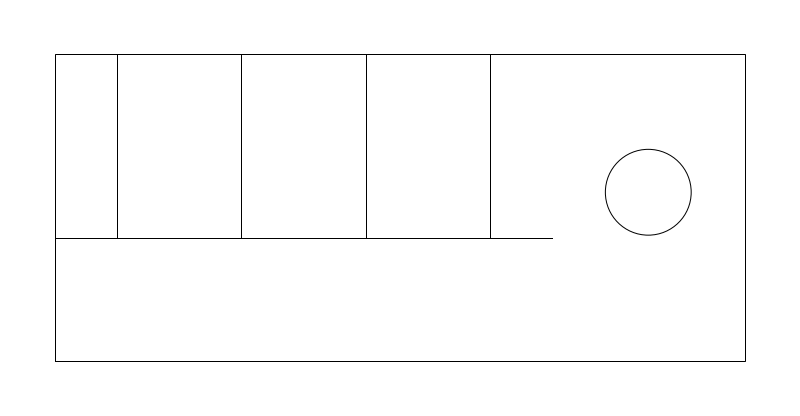
| Plan footprint (W x H) | 4.5in x 2in |
|---|---|
| Units | inches |
| DXF version | R2018 |
| Insertion datum | back-center on wall line (mounted LOW -- CO2 is heavier than air) |
| Parameter | Default | Range / options |
|---|---|---|
| Width | 4.5in | 3in–6in |
| Depth | 2in | 1.5in–3in |
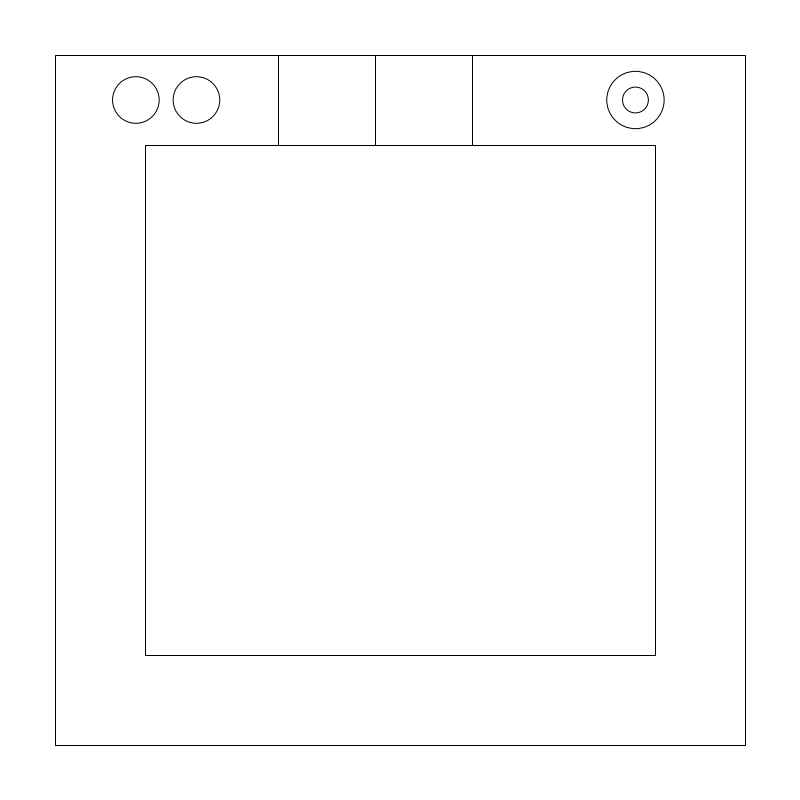
| Plan footprint (W x H) | 30in x 30in |
|---|---|
| Units | inches |
| DXF version | R2018 |
| Insertion datum | back-left corner on wall line |
| Parameter | Default | Range / options |
|---|---|---|
| Width | 30in | 20in–60in |
| Depth | 30in | 20in–60in |
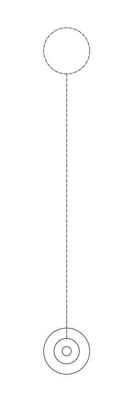
| Plan footprint (W x H) | 14in x 105in |
|---|---|
| Units | inches |
| DXF version | R2018 |
| Insertion datum | post center (belt drawn dashed to the next post at +Y) |
| Parameter | Default | Range / options |
|---|---|---|
| Base | 14in | 12in–18in |
| Belt | 84in | 36in–120in |
Standards are listed for drafting context only. A symbol drawn to a convention is not a compliance determination - verify against the governing code and the specified product. See the license and terms.
Cameras, readers and IT equipment for the security riser and device plan. Open one in the editor or take the DXF.
Every category, every MEP orientation, DXF R2018, sorted into folders. Tell us where to send it and the download starts immediately.
If nothing happened, click here to grab the ZIP.