Twenty-seven electrical conduit CAD blocks: 45 and 90-degree elbows, tee, cross, cap, coupling, reducer, straight run and home run, each in the compass turns or axes it needs. Single-line schematic, the way conduit is drawn on a power plan rather than a piping isometric. Every fitting downloads as a DXF drawn to scale in inches.
9 blocks, 27 downloads on this page. DXF R2018, drawn in inches. Free, no signup.
DWG (R2000, converted from the DXF). PNG is the plan-view preview.
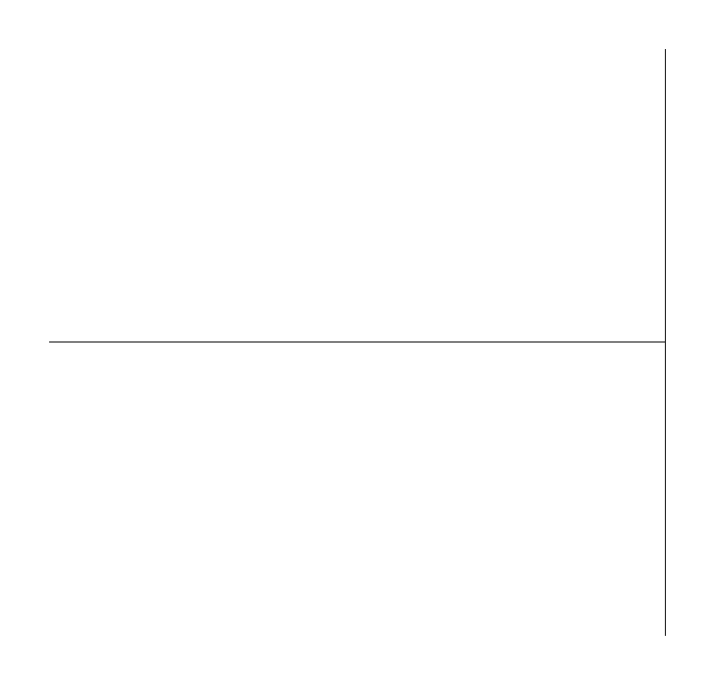
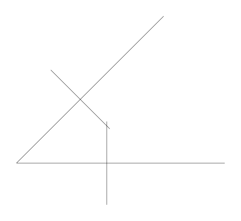
Offsets, kicks and diagonal routing. A 45 is what takes a run around a beam, over a duct, or into a box that does not line up with the raceway centerline. It is also what lets a rack of parallel conduits step to a new elevation together while staying parallel and evenly spaced.
A 45 draws on the same 360-degree allowance a quarter bend does, so two of them equal one 90 against the budget - worth tracking on plan, because an offset built from a pair quietly consumes half the run's allowance. The u parameter sets leg length, 12in default across 6 to 96in, and the default footprint is 12 x 10.9in: the axis leg's width against the diagonal leg's rise. Offset travel works out to 1.414 times the offset distance.
Datum is the bend vertex, one leg on axis and the other running into the named quadrant, so the block aligns to an existing run without shifting it. Drawn alone it reads as a diagonal route change; drawn in pairs it is an offset, and the two symbols should sit close enough on plan that nobody reads them as two independent direction changes.
Nearly always drawn as a mated pair with its opposite-hand variant and a short run between. Where the offset clears another trade, show what it clears - the duct or pipe being stepped over is the whole reason the fitting exists.
| Plan footprint (W x H) | 12in x 10.89in |
|---|---|
| Units | inches |
| DXF version | R2018 |
| Insertion datum | bend vertex (0,0); axis leg + 45deg leg into orient quadrant |
| Parameter | Default | Range / options |
|---|---|---|
| Orientation | NE | NE / NW / SE / SW |
| Nominal size | 12in | 6in–96in |
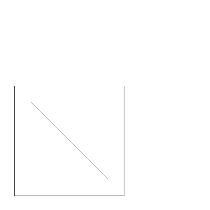
Every change of direction spends bend budget. A raceway run between pull points is limited to 360 degrees total, four quarter bends, so put four of these in series and the next fitting has to be a box. That single constraint is why pull boxes turn up in ceiling locations the architecture gives no reason for.
The u parameter is the leg length the symbol plots at: 12in by default over a 6 to 96in range, measured from the bend vertex out to each port, with the 13.2in square bbox running 1.2in past those ports. It is a schematic radius, not a fabrication one. Real minimum radius comes from NEC Chapter 9 Table 2 by trade size, and long pulls often get factory sweeps or large-radius elbows because conductor sidewall pressure makes the code minimum a poor choice.
Insertion is at the bend vertex rather than at a port, so the elbow drops onto the intersection of two routing centerlines and the legs grow outward from it. Set u for legibility at plot scale, not to anything dimensional. Mirroring produces the other three quadrants, but check port directions afterward - NE and SW are separate blocks, not one block turned around.
Straight runs arrive on both legs, and a pull box or condulet lands wherever accumulated bends reach the limit. On PVC, confirm an expansion coupling has not been placed so close to the bend that it cannot take up movement.
| Plan footprint (W x H) | 13.2in x 13.2in |
|---|---|
| Units | inches |
| DXF version | R2018 |
| Insertion datum | bend vertex (0,0); two ports at u along the two orient dirs |
| Parameter | Default | Range / options |
|---|---|---|
| Orientation | NE | NE / NW / SE / SW |
| Nominal size | 12in | 6in–96in |
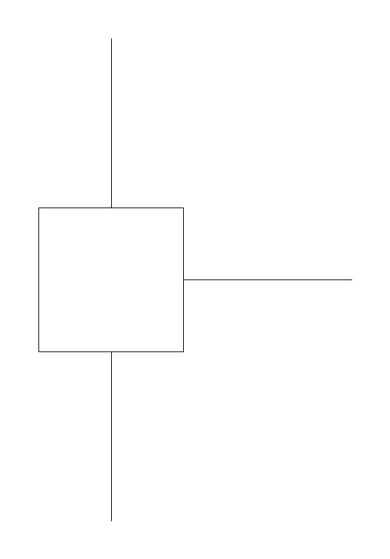
In the piping trades a tee divides flow. In raceway it divides nothing. What this symbol stands for is a Type T conduit body - a condulet - or a junction box with three raceway entries, and its purpose is to give a pulling point and somewhere legal to splice. Saying that plainly heads off a real cross-trade misread.
The u parameter drives the symbol only: 12in default over 6 to 96in, producing a 15.6 x 24in footprint with the run spanning 24in about the origin and the branch stubbing toward the named direction. None of that sizes a fitting. A conduit body follows the trade size it threads onto, its cross-section has to be at least twice that of the largest conduit entering it, and once conductors are spliced inside it must be durably marked with its volume.
Insert at the run center so the run reads continuous through the symbol and only the branch is new geometry. The branch parameter names the stub direction, which makes N, S, E and W four distinct blocks rather than rotations of one - the usual error on a mirrored plan. Tag the fitting type, T or LB or LL or C, because plan geometry alone will never carry it.
A branch circuit leaving a feeder run, most often with a homerun symbol picking up on the stub. Where the splice count outgrows what a conduit body can legally hold, the symbol gets replaced by a junction box.
| Plan footprint (W x H) | 15.6in x 24in |
|---|---|
| Units | inches |
| DXF version | R2018 |
| Insertion datum | run center (0,0); run perpendicular to branch, branch stub +orient |
| Parameter | Default | Range / options |
|---|---|---|
| Branch | E | N / S / E / W |
| Nominal size | 12in | 6in–96in |
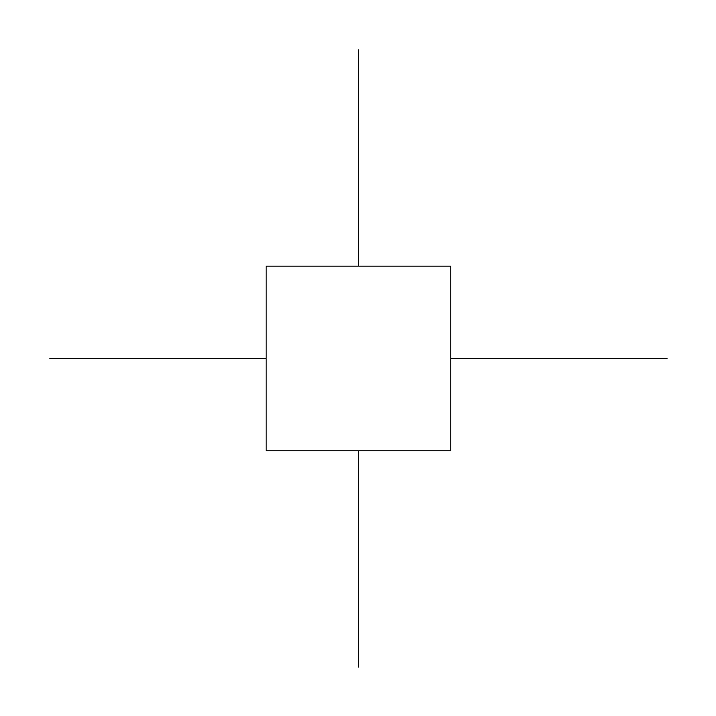
Four raceways meeting at a point. In practice that is a pull box or a junction box rather than a cross fitting - cast crosses exist but are uncommon, and the standard detail is a box with four entries. On plan the symbol marks where the run's bend count resets and where conductors become physically reachable again.
A 24 x 24in footprint at the 12in default, center at (0,0) with ports out east, north, west and south, over a 6 to 96in u range that scales the symbol and nothing else. Real box size comes from the raceways entering it: with conductors 4 AWG and larger, a straight pull is sized at not less than eight times the trade size of the largest raceway and an angle or U pull at not less than six, which at 3in conduit already forces an 18in dimension.
Center insertion keeps the crossing raceways symmetric about the block, so it drops onto the intersection of two routing centerlines. All four ports are identical, so there is no orientation variant and no mirror hazard here. What the symbol cannot tell a reader is whether the four raceways are electrically continuous or merely share an enclosure, so note it.
Sits where two raceway routes cross, each arriving on a straight run and often through an elbow just outside the box. Where it is doing duty as a feeder pull point, it gets read against the panel schedule it feeds.
| Plan footprint (W x H) | 24in x 24in |
|---|---|
| Units | inches |
| DXF version | R2018 |
| Insertion datum | center (0,0); 4 ports E/N/W/S |
| Parameter | Default | Range / options |
|---|---|---|
| Nominal size | 12in | 6in–96in |
The closed end of a raceway: a spare stubbed for future work, a capped underground stub-out waiting on a building addition, or a run deliberately stopped short of a device that is not in this phase. It reads as an instruction more than as a fitting - this run ends here, on purpose.
Note the narrower range. The u parameter runs 6 to 48in here rather than the 96in the routing fittings allow, and the 12in default gives an 8.4 x 8in footprint with the open connection end at (0,0) closing toward the named direction. That is symbol size, not cap size; a cap is a threaded or slip fitting matched to the trade size it closes. Where the stub is future capacity, put trade size and quantity in the note, because that is what a later contractor needs.
The datum sits at the open end, so the block snaps to the last port of a run and grows away from it, the reverse of most terminal symbols. Because it points, orientation is real geometry rather than a rotation, and N, S, E and W are four blocks. Annotate spare raceways with destination and cap elevation. An unlabeled capped stub is worth nothing three years later.
Terminates a straight run, and gets drawn with the sleeve or stub detail wherever it leaves a slab or wall. On underground work it travels with the marking-tape and burial-depth callouts.
| Plan footprint (W x H) | 8.4in x 8in |
|---|---|
| Units | inches |
| DXF version | R2018 |
| Insertion datum | open (connection) end at origin (0,0); closes toward orient |
| Parameter | Default | Range / options |
|---|---|---|
| Orientation | E | N / S / E / W |
| Nominal size | 12in | 6in–48in |
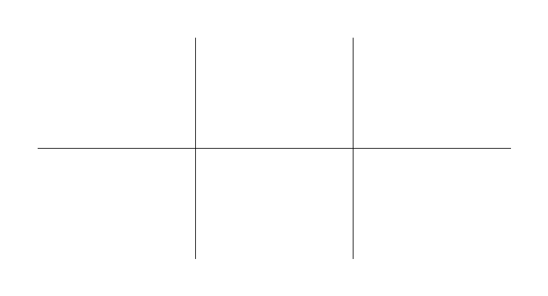
A joint between two lengths of raceway mid-run, drawn where the joint itself carries consequence: a change of raceway type, a transition into a wet or concrete-encased location, or an expansion fitting on a long PVC run. Routine stick-to-stick couplings are not worth showing; these are.
Range here is 6 to 48in, tighter than the routing fittings get, with the 12in default plotting 12 x 5.6in and the left end at (0,0) so the fitting reads mid-run. What the symbol cannot show is coupling type, and type is the entire point: a set-screw EMT coupling is not the concretetight fitting a concrete-encased run requires, and an Erickson or union coupling is what joins two threaded rigid conduits when neither end can rotate.
The left-end datum lets it drop onto a run without shifting the centerline, and because the two ends are symmetric, H and V are the only variants. Use it deliberately - a plan carrying a coupling every 10ft is noise. Where it stands for a PVC expansion fitting, tag it as one and give the piston setting temperature, since that is field-set at install and cannot be inferred afterward.
Straight runs on both sides, plus a bonding jumper wherever the coupling is an expansion or telescoping type that cannot be trusted to carry ground continuity across the joint.
| Plan footprint (W x H) | 12in x 5.6in |
|---|---|
| Units | inches |
| DXF version | R2018 |
| Insertion datum | left end (0,0); coupling mid-run |
| Parameter | Default | Range / options |
|---|---|---|
| Nominal size | 12in | 6in–48in |
| Orientation | H | H / V |
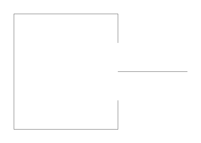
A change in trade size mid-run - stepping a feeder raceway down as circuits drop off it, or coming out of a large stub-up into the smaller conduit the devices actually need. In the field the reduction is usually a reducing bushing or a pair of reducing washers at an enclosure rather than a cast fitting.
The LARGE end sits at (0,0) and the raceway reduces along +X, which matters because this block is directional and not symmetric. The u parameter defaults to 12in across 6 to 96in on a 12 x 8in footprint and governs how big the symbol draws, nothing else; it names neither trade size. Both belong in the tag, large first. Trade sizes run 1/2 through 6in in the Chapter 9 tables, though EMT itself stops at 4in.
Because the datum is the large end, mirroring for a reversed run also flips the reduction direction. Verify which end is which after any mirror; a reducer drawn backwards is a fill error nobody catches until the pull. Where the reduction actually happens at an enclosure hub or inside a junction box, draw the box and drop the fitting entirely.
A larger run on the datum side and a smaller one leaving, usually with the branch or device that justified the step-down close by. Where the reduction lands at an enclosure, the box symbol takes over and the reducing washers become a note.
| Plan footprint (W x H) | 12in x 8in |
|---|---|
| Units | inches |
| DXF version | R2018 |
| Insertion datum | LARGE end at origin (0,0); reduces along +X (H) / +Y (V) |
| Parameter | Default | Range / options |
|---|---|---|
| Orientation | H | H / V |
| Nominal size | 12in | 6in–96in |
The plain length of raceway between fittings: the segment that carries conductors across a ceiling, down a wall or through a slab. On a power plan it is the connective tissue between homeruns and devices. On a coordination drawing it is the item fighting duct, sprinkler main and gravity pipe for the same ceiling space.
Length runs 6 to 480in, so one insert covers a nipple between two boxes or a 40ft straight shot down a corridor. The block plots as a zero-height line, 12in x 0 at the default, snapping to a routing centerline with no body of its own. Nothing in the geometry implies trade size or conductor count. Both belong in the callout, and both are what decide fill and ampacity adjustment.
Left end at (0,0) running +X makes chaining trivial: set the length, start the next segment where the last one ended. With no height in the bbox, endpoint snap is the only dependable grab - there is no face to catch midway. Keep raceway on a layer separate from circuiting polylines or the takeoff double-counts every foot.
Terminates into couplings, elbows and condulets, and picks up support or hanger notes wherever it crosses structure. Long parallel runs get racked together and dimensioned as a group rather than one at a time.
| Plan footprint (W x H) | 12in x 0in |
|---|---|
| Units | inches |
| DXF version | R2018 |
| Insertion datum | left end (0,0); pipe/duct runs +X to (length,0) |
| Parameter | Default | Range / options |
|---|---|---|
| Length | 12in | 6in–480in |
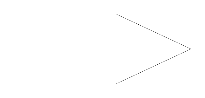
Not a fitting at all - an annotation. The arrow declares that this raceway leaves the drawn area and returns to a panel, and the tag beside it names the panel and the circuit numbers. It is the symbol that binds a power plan to the panel schedule, and the only conduit symbol whose meaning is entirely textual.
Device end at (0,0) with the arrow pointing toward the panel, 12 x 4.7in at the 12in default over a 6 to 96in range; the height above the run line is the arrowhead and the conductor tick marks. Scale it for legibility at plot scale and nothing else. Conductor count comes from the ticks and the tag - long tick for ungrounded, short tick for grounded, with the equipment grounding conductor usually called out in text rather than ticked.
Direction is meaning here, not appearance: the arrow has to point toward the panel, so the four orientation variants are not interchangeable and a mirrored plan needs the homerun re-picked rather than flipped. Keep the circuit tag on the symbol's layer so schedule edits travel with it. Two circuits sharing one raceway is one homerun with two circuit numbers, not two symbols.
Begins at the first device on the circuit and points toward a panel usually drawn on another sheet, which is why the tag carries the panel name. Read it against the panel schedule; a circuit on plan but absent there is the classic coordination miss.
| Plan footprint (W x H) | 12in x 4.73in |
|---|---|
| Units | inches |
| DXF version | R2018 |
| Insertion datum | device end at origin (0,0); arrow points toward orient (panel) |
| Parameter | Default | Range / options |
|---|---|---|
| Orientation | E | N / S / E / W |
| Nominal size | 12in | 6in–96in |
Standards are listed for drafting context only. A symbol drawn to a convention is not a compliance determination - verify against the governing code and the specified product. See the license and terms.
Single-line fittings for the power and lighting plan. Open one in the editor or take the DXF.
Every category, every MEP orientation, DXF R2018, sorted into folders. Tell us where to send it and the download starts immediately.
If nothing happened, click here to grab the ZIP.