Duplex receptacle, 220V receptacle, single-pole light switch and the electrical panel they home run to - four electrical CAD blocks that carry most of a residential or light commercial power plan. Device symbols are drawn at plan scale rather than to the physical device size, which is the convention these follow. Free DXF downloads.
4 blocks, 4 downloads on this page. DXF R2018, drawn in inches. Free, no signup.
DWG (R2000, converted from the DXF). PNG is the plan-view preview.

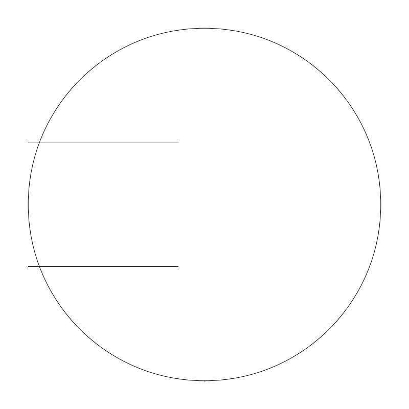
The workhorse of any power plan: two NEMA 5-15R or 5-20R receptacles in one device box. Drafters place dozens per floor, and the raw count drives circuit quantity, panel size and furniture-power coordination with the interiors set.
A single-gang plate over the real device is under 3in wide. The 8in circle at the 4in default is deliberate oversizing so the symbol survives an 1/8in = 1ft-0in plot, and every other electrical symbol on the sheet scales off the same r, so changing one means changing the family.
The circle sits a full radius above the origin with a short stub tying it back to the wall line, so you insert at the wall and the symbol reads into the room. Mirror rather than rotate across a corridor, or the circle ends up on the far side of the partition. GFCI, WP and switched-half are tag and legend conventions layered onto this same block, not separate geometry.
Sits one level below the panel in the drawing hierarchy. Homerun arcs gather groups of these back to a single panelboard, and the arc count is the first thing a reviewer scans.
| Plan footprint (W x H) | 8in x 8in |
|---|---|
| Units | inches |
| DXF version | R2018 |
| Insertion datum | wall-mount point on wall line |
| Parameter | Default | Range / options |
|---|---|---|
| Radius | 4in | 2in–8in |
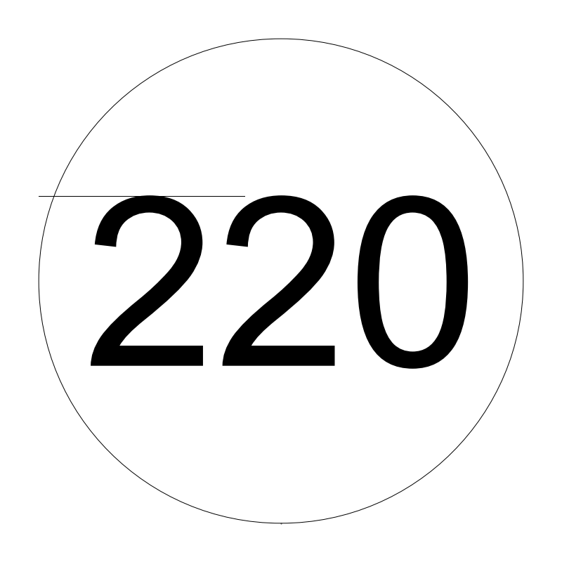
A dedicated high-draw receptacle for a range, dryer, welder, EV charger or shop tool: the one that gets its own homerun and its own line on the panel schedule. Residential plans show a handful of them, in laundry, kitchen and garage.
220V is shop shorthand. Nominal single-phase is 120/240V, or 208V taken across two legs of a three-phase wye. Configuration is what actually has to reach the field, NEMA 14-50 for a range or an EV charger, 14-30 for a dryer, 6-50 for a welder, and none of that comes from r, which only scales the circle.
The only geometric difference from the duplex is a third blade tick, so the block carries a 220 tag inside the circle to keep the distinction alive at an 1/8in plot. Put the NEMA configuration in the tag beside it. Insert on the wall line and rotate the stub into the room; on the wrong side of a partition the rough-in lands in the neighboring space.
Read against the panel. Each of these is a two-pole breaker, so a handful of them eats the spare capacity a residential load center was sized with.
| Plan footprint (W x H) | 8in x 8in |
|---|---|
| Units | inches |
| DXF version | R2018 |
| Insertion datum | wall-mount point on wall line |
| Parameter | Default | Range / options |
|---|---|---|
| Radius | 4in | 2in–8in |
The letter S controlling a lighting circuit from one location. It carries no geometry and all of its meaning; the real work is putting it on the correct side of a door swing.
The 5.2 x 7.2in extents are glyph metrics rather than a device footprint, because the letter is the entire symbol. r sets the text height at 1.4r, so match it to the sheet's annotation text height or the S either disappears at plot or shouts over the fixture symbols.
Insert on the wall line and keep the letter upright no matter how the wall runs, since text symbols are never rotated to follow geometry. The block deliberately ships with no wall stub and no switch leg: the leg belongs to the wiring on the plan, not to the device. Type is carried by subscript, S3 for three-way and S4 for four-way, with dimmer and occupancy-sensor variants defined in the legend.
Meaningless alone. Draw it with the fixture it controls and join the two with the curved switch-leg arc, which you add yourself since the block does not carry one.
| Plan footprint (W x H) | 2.72in x 0.88in |
|---|---|
| Units | inches |
| DXF version | R2018 |
| Insertion datum | wall-mount point on wall line |
| Parameter | Default | Range / options |
|---|---|---|
| Radius | 4in | 2in–8in |
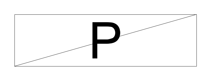
The load center or panelboard where every homerun on the sheet terminates. Residential plans carry one in a garage or utility room; commercial sets carry several per floor, each keyed to a schedule of breaker sizes and connected load.
The 14in default is a typical residential load-center width, and the range reaches 42in for commercial panelboards and distribution sections. Depth 3-8in covers surface and flush cans, but a flush unit buries most of that in the stud cavity, so width is the number that governs wall layout. The published 4.2in at a 4in depth setting is the P tag reading a fraction below the wall line, not extra can.
The block plots as a solid-filled bar, which is the panelboard convention; if it renders as an outline with a P inside, your viewer is not drawing SOLID entities. Back-center insertion puts the datum on the wall face so it snaps to a wall line and rotates about the mounting surface. Most offices add the working space in front as a dashed rectangle, since that zone collides with shelving, door swings and stored equipment.
Every receptacle, switch and lighting symbol on the sheet resolves here, so the panel goes down first and the homeruns are routed back to it.
| Plan footprint (W x H) | 14in x 4in |
|---|---|
| Units | inches |
| DXF version | R2018 |
| Insertion datum | back-center on wall line |
| Parameter | Default | Range / options |
|---|---|---|
| Width | 14in | 12in–42in |
| Depth | 4in | 3in–8in |
Standards are listed for drafting context only. A symbol drawn to a convention is not a compliance determination - verify against the governing code and the specified product. See the license and terms.
Receptacles, switches and the panel for the power plan. Open one in the editor or take the DXF.
Every category, every MEP orientation, DXF R2018, sorted into folders. Tell us where to send it and the download starts immediately.
If nothing happened, click here to grab the ZIP.