Tee, cross, cap, transition and straight run - the HVAC duct CAD blocks that connect the elbows into a run - plus the ceiling exhaust grille the run terminates at. Tees and caps ship in all four compass directions, and the transition and run come horizontal and vertical, for fourteen downloads across six base fittings. Double-line, parametric on duct width, drawn to scale in inches.
6 blocks, 14 downloads on this page. DXF R2018, drawn in inches. Free, no signup.
DWG (R2000, converted from the DXF). PNG is the plan-view preview.
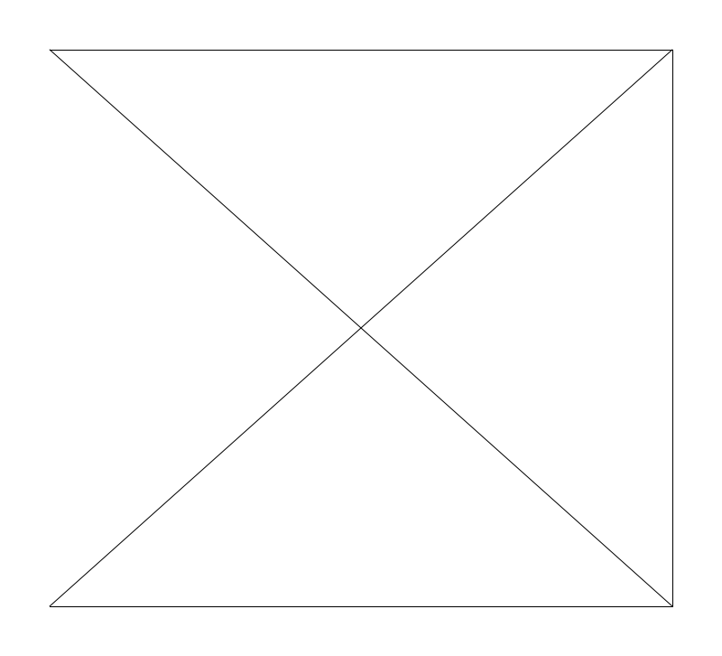
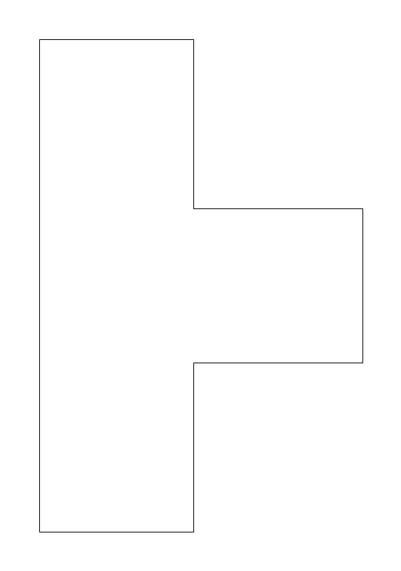
Branch takeoff on a trunk - a zone duct leaving a main, a drop to a diffuser, or on the return side two streams merging into one. Balance is won or lost at the branch, which is why this fitting carries more annotation per inch of duct than anything else on a mechanical sheet.
u sets the run half-length and the branch reach, width sets every duct dimension, giving 21 x 32in at defaults. The symbol draws branch and run at the same width, which is almost never built - a branch is sized for its own airflow - so tag both. Junction loss follows the flow split and the branch-to-trunk velocity ratio, not the drawn proportions.
Datum is run center and the branch parameter is takeoff direction only, so it does not reorient the run. The drawn tap is square-cut, the worst case for branch loss: a 45-degree entry, or a conical tap where the branch is round, has to be specified in a note. Show the balancing damper near the takeoff and well upstream of the terminal.
Feeds a run that ends at a diffuser drop or a cap, and four tees worked around a trunk beat one cross for control. Where the branch crosses a rated wall or shaft it picks up a fire damper and the access door needed to reach it.
| Plan footprint (W x H) | 21in x 32in |
|---|---|
| Units | inches |
| DXF version | R2018 |
| Insertion datum | run center (0,0); run perpendicular to branch, branch stub +orient |
| Parameter | Default | Range / options |
|---|---|---|
| Branch | E | N / S / E / W |
| Nominal size | 16in | 6in–96in |
| Width | 10in | 4in–48in |
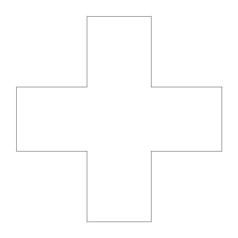
Four ports off one node: a trunk splitting three ways, or two mains meeting. Worth saying plainly that this is uncommon as a fabricated rectangular fitting - most four-way nodes get built as a plenum box or as two takeoffs back to back, and the symbol is a schematic stand-in for either.
Symmetric by construction, 2u across both axes for 32 x 32in at u=16, all four arms drawn at width with the central square left open where the throats break the walls. That symmetry is the trap, because equal geometry does not divide flow equally. The leg the incoming air is already aimed at takes the larger share, so every leg needs a design airflow and a damper to hold it.
Center datum and no orientation parameter, so nothing in the block records which arm is the inlet - put an airflow arrow on it or the node is ambiguous to everyone downstream. Do not reach for it where two ducts merely cross at different elevations. That is a crossover, drawn with one duct broken at the gap, and joining them here reads as a fabrication instruction nobody intended.
Reads against two tees set back to back, which is how the same junction usually gets detailed and built. Its arms run out to straight runs, and any arm roughed in for future work terminates in a cap rather than being left open.
| Plan footprint (W x H) | 32in x 32in |
|---|---|
| Units | inches |
| DXF version | R2018 |
| Insertion datum | center (0,0); 4 ports E/N/W/S |
| Parameter | Default | Range / options |
|---|---|---|
| Nominal size | 16in | 6in–96in |
| Width | 10in | 4in–48in |
Closes the end of a duct. It turns up at the terminus of a main past the last takeoff, on a leg roughed in for a future tenant fit-out, and at the temporary end of a section being leakage tested before the next phase ties into it.
width is the real duct dimension while u only scales the stub, which draws at 0.7u for an 11.2in body at the default u=16, so the footprint is a symbol and not a fabricated cap. On a wide duct that flat blank-off is an unsupported panel taking full system pressure and wants cross-breaking or a stiffener, or it deflects and drums. Placement beats size: hold the cap a stub past the last branch so the final takeoff sees moving air.
Datum is the open connecting end, so the block snaps onto a run and closes away from it; orient is simply which way it closes. The X across the stub is the blank-off marker, not a crossing duct. Tag capped-for-future differently from capped-permanent - the future one needs its size, its design airflow and the damper behind it, or the next drafter has nothing to reconnect to.
Terminates a straight run one stub past the last tee, and closes any spare arm left on a cross. On a phased job it doubles as the test blank, sealed while the section is pressurized, then cut off when the next phase arrives.
| Plan footprint (W x H) | 11.2in x 10in |
|---|---|
| Units | inches |
| DXF version | R2018 |
| Insertion datum | open (connection) end at origin (0,0); closes toward orient |
| Parameter | Default | Range / options |
|---|---|---|
| Orientation | E | N / S / E / W |
| Nominal size | 16in | 6in–48in |
| Width | 10in | 4in–48in |
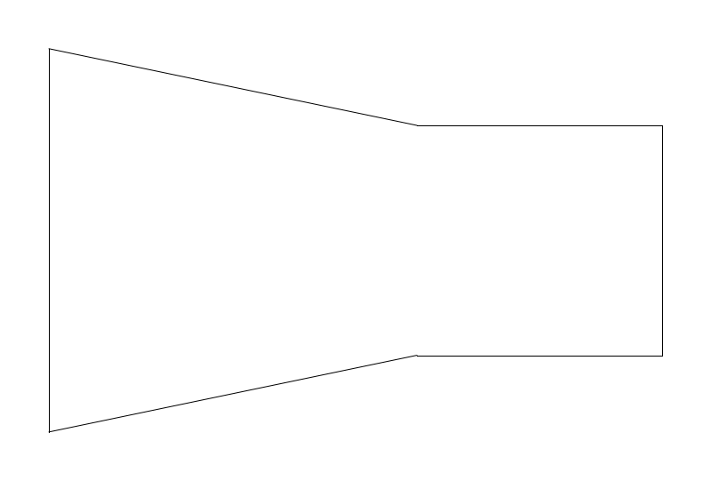
Where the duct changes size: a trunk stepping down past a takeoff, a fan or coil connection that does not match the run it feeds, or a squeeze past a beam with the area handed back on the far side. Small fitting, and the place where fan performance is most often quietly lost.
The large end sits at the origin and the duct reduces along +X, so an expansion is drawn by mirroring rather than rotating. width is the large dimension and the small end is locked at 60 percent of it - there is no second size parameter. The taper body runs 0.6u, which puts the wall near 12 degrees per side at default proportions; stretching u is what flattens it.
Reducing one dimension only is the normal ceiling case since depth is pinned by the cavity, so note which one moves: 24x12 to 18x12 and 24x12 to 24x9 are the same area change and entirely different sheet metal. Common guidance keeps a diverging transition near 15 degrees included and lets a converging one open toward 30, so the drawn default reads fine as a contraction and steep as an expansion.
Lands on a straight run just downstream of a tee, where the trunk has given up the branch airflow and steps down to suit. The other habitual spot is between an air handler or coil connection and the first full-size run.
| Plan footprint (W x H) | 16in x 10in |
|---|---|
| Units | inches |
| DXF version | R2018 |
| Insertion datum | LARGE end at origin (0,0); reduces along +X (H) / +Y (V) |
| Parameter | Default | Range / options |
|---|---|---|
| Orientation | H | H / V |
| Nominal size | 16in | 6in–96in |
| Width | 10in | 4in–48in |
Trunk and branch straightaway on a supply, return or exhaust layout. Fittings are short, so most of the linear footage on a duct plan is this block, and it carries the annotation everything downstream inherits: duct size, pressure class, liner or wrap, and the airflow the segment was sized for.
width is the dimension across the run and length reaches 480in, so a single insert covers a 40ft trunk. Aspect ratio is the number worth watching. At constant free area, going from square to 4:1 adds about a quarter to the perimeter and 8:1 adds close to 60 percent, and that is sheet metal, hanger load, insulation and friction surface all climbing together for the same CFM.
The block draws both sidewalls plus a face line at each end, so two runs butted together show a line at the joint. The built duct is not one piece either: transverse joints land at the 4 or 5ft sheet length and hangers commonly run 8 to 10ft, so a 40ft insert is eight to ten fabricated sections. Note pressure class on the run, since gauge and reinforcement follow from it and not from the width.
Every fitting in this family lands on the end of one of these, and the size tagged here is what the elbow, tee and transition inherit. Two runs meeting at a corner stay unconnected until a 90-degree elbow is dropped on the vertex.
| Plan footprint (W x H) | 16in x 10in |
|---|---|
| Units | inches |
| DXF version | R2018 |
| Insertion datum | left end (0,0); pipe/duct runs +X to (length,0) |
| Parameter | Default | Range / options |
|---|---|---|
| Length | 16in | 6in–480in |
| Width | 10in | 4in–48in |
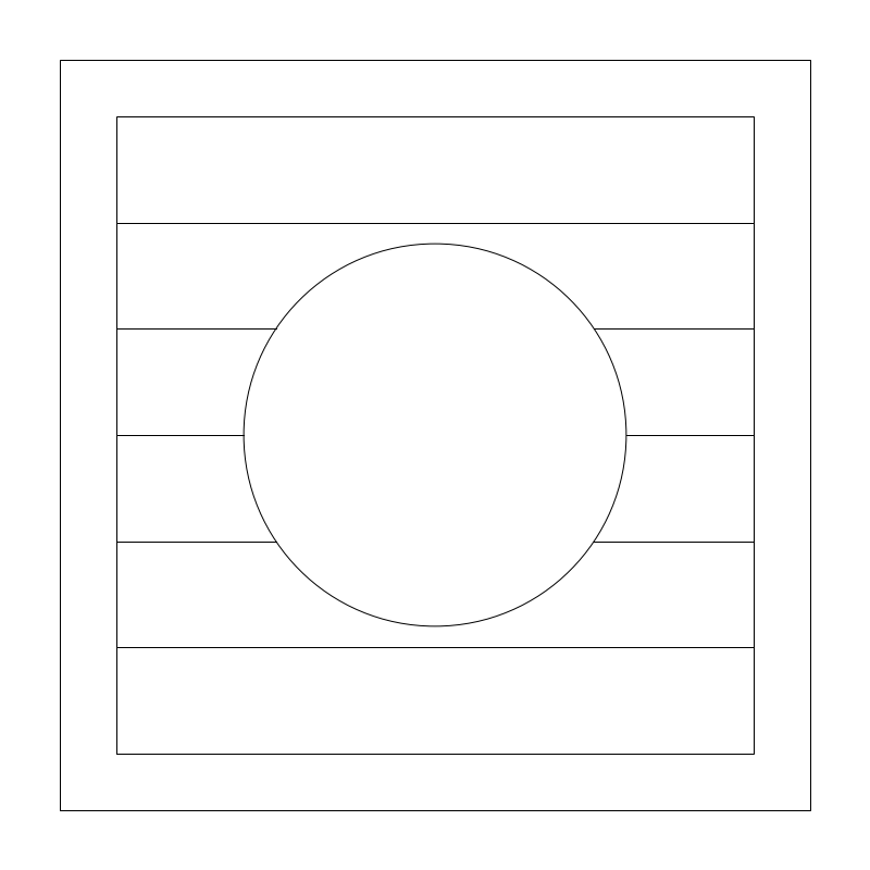
| Plan footprint (W x H) | 12in x 12in |
|---|---|
| Units | inches |
| DXF version | R2018 |
| Insertion datum | grille center (0,0) at the ceiling; also the duct-connection point |
| Parameter | Default | Range / options |
|---|---|---|
| Size | 12in | 6in–24in |
| Neck | 8in | 4in–16in |
Standards are listed for drafting context only. A symbol drawn to a convention is not a compliance determination - verify against the governing code and the specified product. See the license and terms.
Size the duct once and every fitting follows, right through to the grille it ends at. Open one in the editor or take the DXF.
Every category, every MEP orientation, DXF R2018, sorted into folders. Tell us where to send it and the download starts immediately.
If nothing happened, click here to grab the ZIP.