The 45-degree and 90-degree HVAC duct elbow CAD blocks, each drawn in all four compass turns - northeast, northwest, southeast, southwest - so the fitting on the sheet points the way the run actually goes. Duct is double-line parametric here, not a single-line schematic, so the width you set is the width that plots. Eight DXF downloads across two base blocks.
2 blocks, 8 downloads on this page. DXF R2018, drawn in inches. Free, no signup.
DWG (R2000, converted from the DXF). PNG is the plan-view preview.
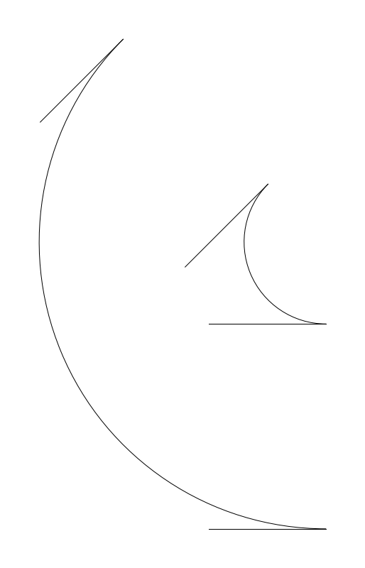
Used far more often as half of an offset than as a turn in its own right. Two of them with a short run between shift a trunk sideways past a beam, a light fixture or another trade's line, at a fraction of the pressure loss and the corner clearance a pair of 90s would demand.
One leg lies on axis and the other on the diagonal, so the footprint is lopsided at 14 x 23.9in for u=16, width=10, and those extents come off the swept walls rather than the leg length. Sharing the same fixed 4in inside corner as the 90, the bend center sits (4 plus width/2) over sin 22.5 degrees from the vertex, roughly 23.5in at defaults.
Bend vertex is the datum, same as the 90, so an offset is built by inserting this block, a run, then the opposite-quadrant variant. Give that intermediate run real length. Two bends stacked nose to tail leave the second working in a distorted velocity profile, and published loss coefficients all assume an approach that is not already swirling.
Comes in mirrored pairs with a straight run between, the NE variant working against the SE or NW depending which way the trunk shifts. Where the offset also changes duct size, the transition belongs on that run, not on either bend.
| Plan footprint (W x H) | 30.85in x 19.85in |
|---|---|
| Units | inches |
| DXF version | R2018 |
| Insertion datum | bend vertex (0,0); axis leg + 45deg leg into orient quadrant |
| Parameter | Default | Range / options |
|---|---|---|
| Orientation | NE | NE / NW / SE / SW |
| Nominal size | 16in | 6in–96in |
| Width | 10in | 4in–48in |
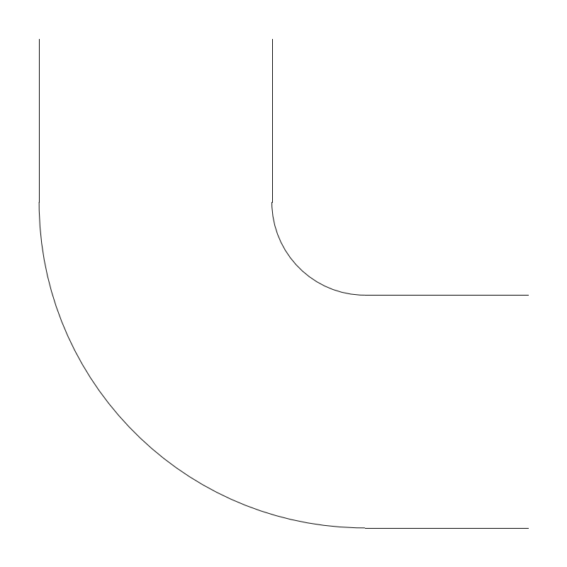
A square-duct 90-degree turn, drawn where the trunk follows the building around a column, a beam line or a shaft wall. On the air side it is usually the most expensive single fitting in the run, so the throat treatment - radius, miter, vanes - belongs in a note rather than left to the fabricator.
u is the leg length from bend vertex to each port and width is the duct dimension, so the footprint is u plus half a width on both axes: 21in square at u=16, width=10. Throat radius is not a parameter. The block sweeps concentric walls off a fixed 4in inside corner, so the drawn centerline R/W works out to 0.5 plus 4/W - about 0.9 on a 10in duct, 0.58 on a 48in one.
Insert on the intersection of two centerlines; the vertex is the datum and the outer wall swings half a width past it. Draw the elbow you intend to build. At R/W 1.5 a 36in duct puts the tangent point 54in back from the corner on each leg, a real clash with structure and the whole reason mitered-and-vaned elbows exist. Vanes get called out, never inferred.
Sits between two straight runs and takes their tagged size. Where the turn is really an offset around an obstruction, a mirrored pair of 45s replaces it. Vane and rail construction comes off the SMACNA plates, not out of this symbol.
| Plan footprint (W x H) | 21in x 21in |
|---|---|
| Units | inches |
| DXF version | R2018 |
| Insertion datum | bend vertex (0,0); two ports at u along the two orient dirs |
| Parameter | Default | Range / options |
|---|---|---|
| Orientation | NE | NE / NW / SE / SW |
| Nominal size | 16in | 6in–96in |
| Width | 10in | 4in–48in |
Standards are listed for drafting context only. A symbol drawn to a convention is not a compliance determination - verify against the governing code and the specified product. See the license and terms.
Duct width and radius are parameters. Open one in the editor, size it to the run, then export the DXF.
Every category, every MEP orientation, DXF R2018, sorted into folders. Tell us where to send it and the download starts immediately.
If nothing happened, click here to grab the ZIP.